32
4
SYSTEMA EOLO RT rev. 09ENIT04052021
ELECTRICAL CONNECTION
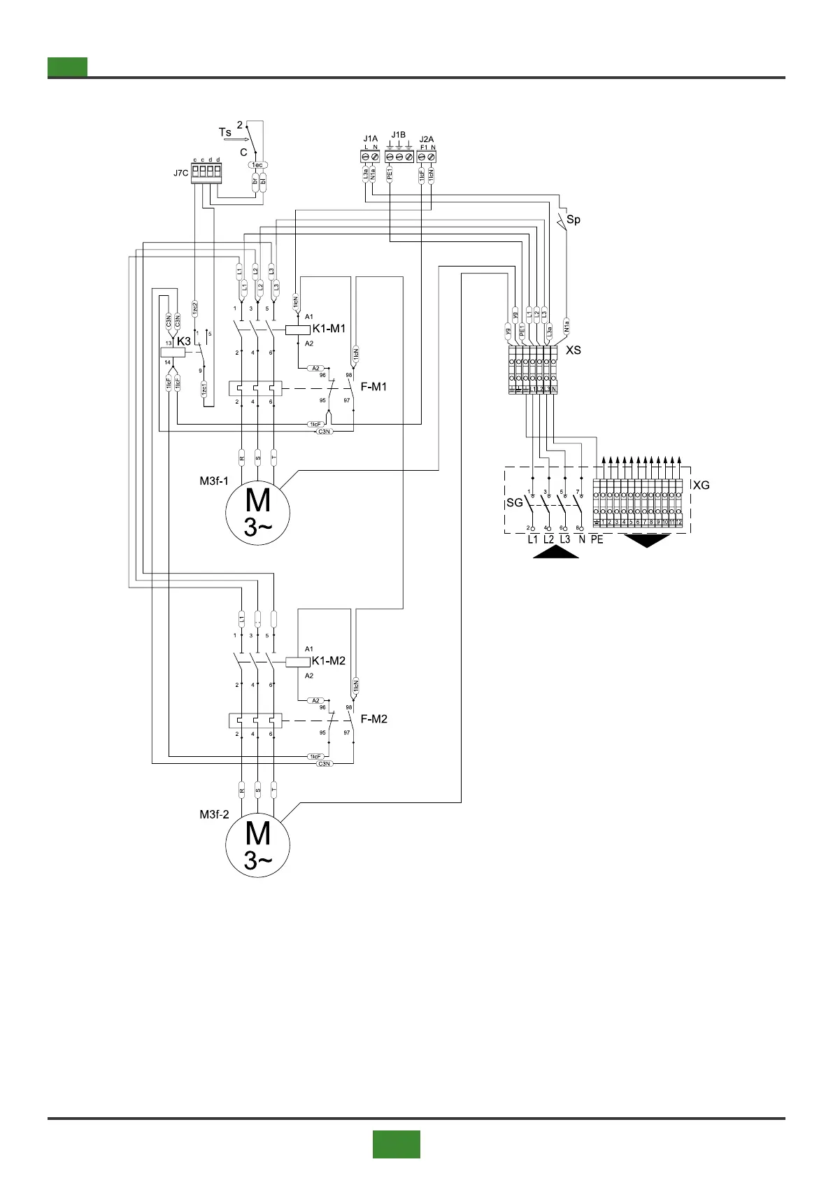
4.1.4 4.1.4 Wiring diagram with two fans and three-phase AC asynchronous motors
POWER SUPPLY
3N/PE~50Hz 400V
Fig 4.4 Wiring diagram for appliances with two fans
ROOM CONTROL
PANEL
(see g. 4.2 p. 30)
Legend gs. 4.3 and 4.4
ACC = Ignitor
Bp = Premix burner
Em = Ground electrode
EV = Solenoid valve
F1 = Fan protection fuse (J2A)
F2 = Fan protection fuse (J2B)
F3 = Burner protection fuse
F4 = Fuse burner protection
F5 = Fuse auxiliary protection J5B - J6B
F-M1 = Fan thermal protection
F-M2 = Second fan thermal protection
TSM = High votage transformer
Hd = Display with icons and symbols of the burner status
K3 = Relay securities
K1-M1 = Fan contactor
K1-M2 = Second fan contactor
M3f-1 = Three-phase centrifugal fan motor
M3f-2 = Second three-phase centrifugal fan motor
P3 = Probe NTC 100 inlet air ow temperature