69
8
SYSTEMA EOLO RT rev. 09ENIT04052021
COLLAUDO
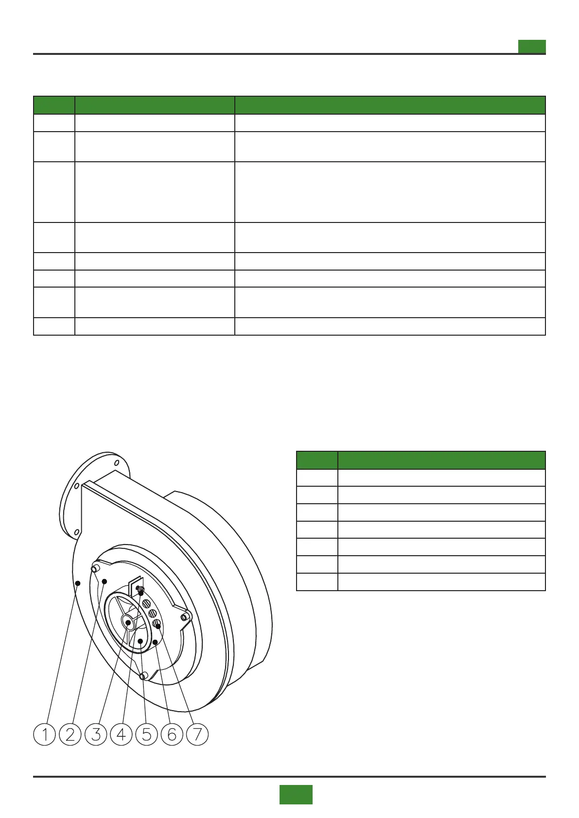
Fig. 8.3 Burner fan
Tab. 8.3 Burner fan legend
Tab 8.2 Key to solenoid valve 822 Nova Mix
POS. DESCRIPTION OPERATING INSTRUCTION
1 Gas inlet
2 Inlet gas pressure intake
Point for measuring the supply gas pressure.
The gas supply pressure must not exceed 50 mbar
3 Outlet gas pressure in OUTPUT
Point for measuring the burner gas pressure.
In the pre-wash procedure, a depression proportional to the speed of the fan is de-
tected.
During operation, the outlet gas pressure is detected.
4 Off set regulator
Internal hexagonal screw for adjusting the minimum gas ow rate.
Adjust the CO2, CO, NO valuesX in combustion at minimum power
5 Electrical connectors
6 Gas outlet
7 Maximum gas ow regulator
Maximum gas ow adjustment screw.
Adjust the CO2, CO, NO valuesX in combustion at maximum power
8 Solenoid valve 822 NOVA MIX
POS. DESCRIPTION
1 Fan
2 Air / gas mixer
3 Gas inlet
4 Secondary air regulator tightening screw
5 Primary air inlet
6 Secondary air regulator
7 Secondary air inlet
8.3.3 8.3.3 Air mixer (Eolo BC / BL 15 ÷ 120 RT)
The air - gas mixer placed upstream of the burner fan (Eolo BC / BL 15 ÷ 120 RT), introduces the right volume
of air and gas into it.
The air regulation must not be modied unless indicated by the manufacturer.