70
8
SYSTEMA EOLO RT rev. 09ENIT04052021
COLLAUDO
5
10
1
9
12
10
11
8
9
3
2
6
8.3.4 Adjustment of burner parameters with solenoid valve type VR4 ... (Eolo 150 ÷ 300)
After the burner activation phase, it is necessary to check ignition at the minimum regulated output of the bur-
ner. If there are problems with ignition, correct the CO2 setting with the solenoid valve. If the burner produces
resonances at minimum power, it will be possible to make adjustments by making appropriate adjustments to
the air / gas ratio.
After the rst ignition, carry out a combustion analysis and verify the correctness of the combustion itself.
When leaving the factory, Eolo appliances are always checked in terms of safety, thermal power and combu-
stion parameters. However, always check the parameters in paragraph 8.5 on page 91 during commissioning.
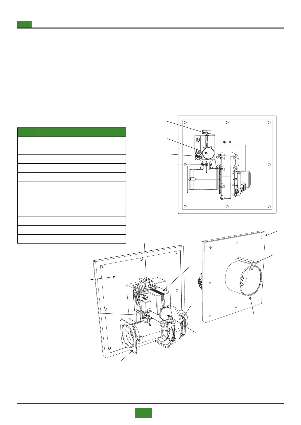
POS. DESCRIPTION
1 Burner base
2 Burner head
3 Electrodes
4 Burner plate insulation
5 VR4 solenoid valve ...
6 EBM gas blower
7 VMU Venturi mixer ...
8 Gas connection
9 Maximum pressure adjustment
10 "OFFSET" minimum pressure adjustment
11
Measurement of the gas pressure on the burner
12 Pressure measurement at the supply
Fig. 8.4 Adjustment of the burner parameters in the
Eolo BC / BL 150 ÷ 300 RT models
Tab. 8.4