64
7
SYSTEMA EOLO RT rev. 09ENIT04052021
INSTALLAZIONE
Pay particular attention to the construction of the condense conveying pipes; incorrect piping can compromise the cor-
rect operation of the appliance.
For the construction of the condense conveying pipes, use materials suitable to withstand the mechanical, thermal and
chemical stresses of the condense over time (for example stainless steel pipes or plastic material for the passage of
cold water).
Do not use copper or iron pipes, materials that are easily attacked and perishable by the acidity of the condensate.
7.4 CONDENSATE DRAIN
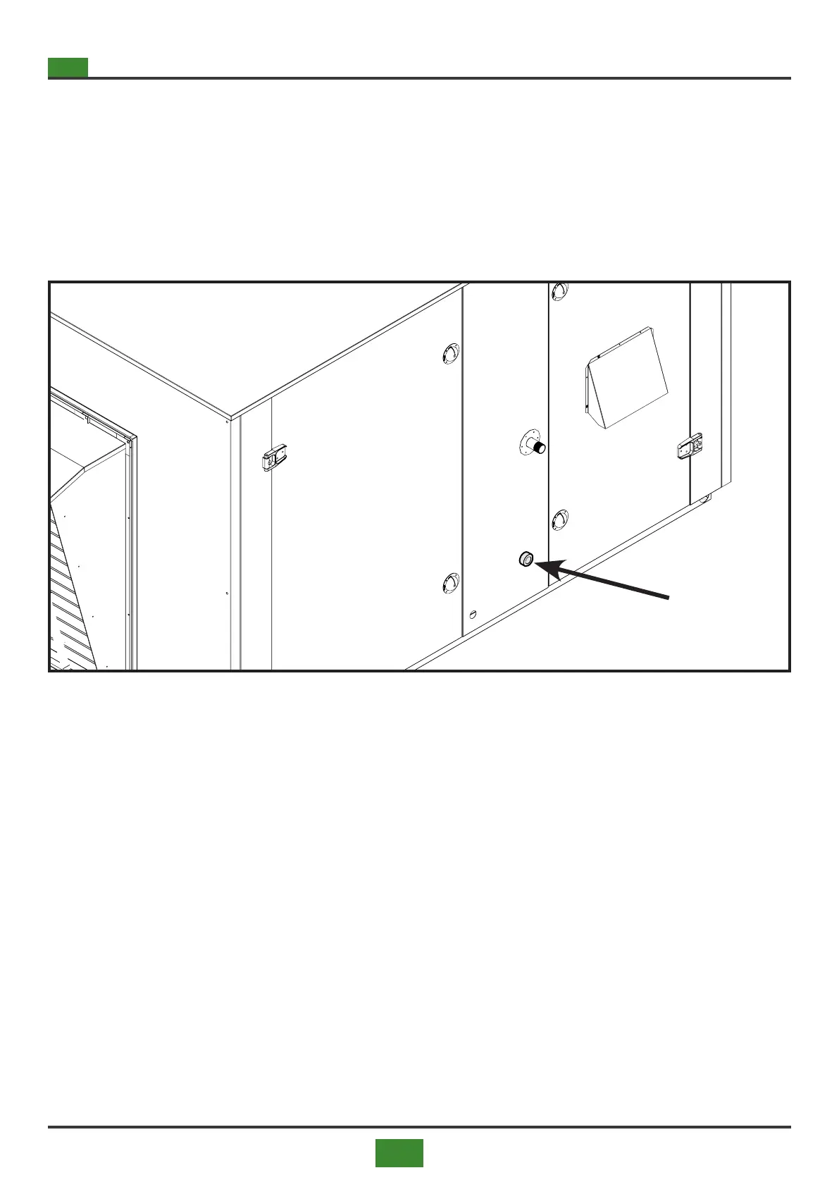
Fig. 7.7 Position of the condensate drain connection
7.4.1 Condensate drain connection
The appliances are equipped with a condensate drain connection on the side of the machine, under the gas
pipe connection. The factors to be taken into consideration when constructing the condensate drain piping
are:
■ avoid the stagnation of condensate inside the exchanger;
■ avoid the stagnation of condensate inside, except for the liquid head present in the siphon or similar de-
vice;
■ avoid freezing of condensation water in the pipeline;
■ avoid the discharge of fumes and / or unburnt gases through the condensate pipe;
■ compensate for any pressure variations inside the sewerage network or other evacuation collection sy-
stem where the drain is connected such as to aect the operating conditions of the appliance or gas
system;
■ for the correct disposal of the combustion condensates, it is necessary to assess whether the current
legislation requires the need to neutralize the condensates with a special system.
7.4.2 Condensate stagnation in the exchanger
■ Install the appliance perfectly level to maintain the natural inclination of the tube bundle and allow the
condensate to drain, preventing it from accumulating inside the exchanger during normal operation