68
8
SYSTEMA EOLO RT rev. 09ENIT04052021
COLLAUDO
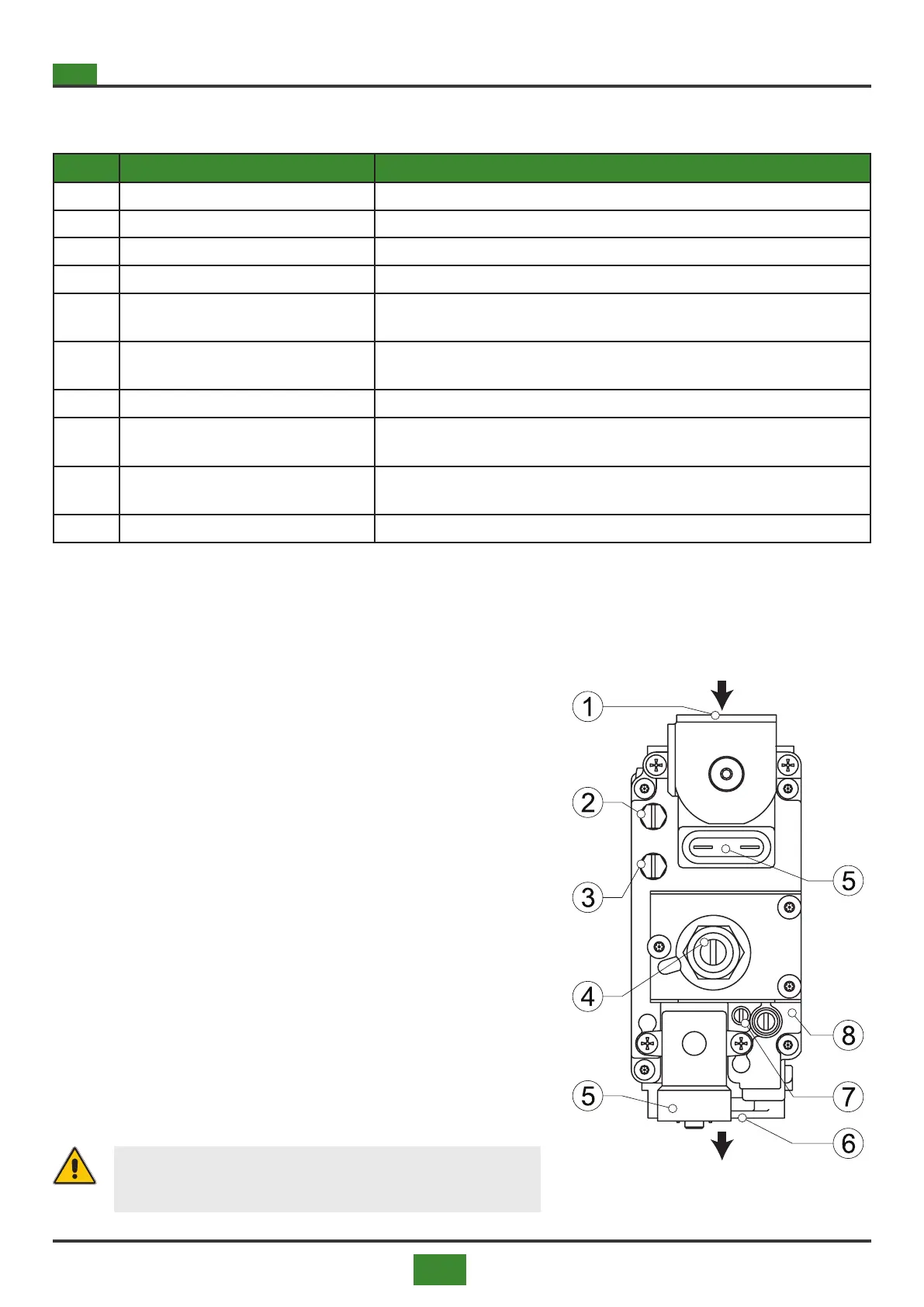
Tab 8.1 Key to 848 Sigma solenoid valve
POS. DESCRIPTION OPERATING INSTRUCTIONS
1 Solenoid valve 848 SIGMA
2 Electrical connector
3 Gas inlet
4 Gas outlet
5 Inlet gas pressure intake
Point for measuring the supply gas pressure. The gas supply pressure must not exceed
50 mbar
6 Intermediate gas pressure intake
Point for detection of the burner gas pressure. In the pre-wash procedure, a depression
proportional to the speed of the fan is detected.
7 Vacuum signal connection Not used NB must remain completely open
8 Maximum gas ow regulator
Maximum gas ow adjustment screw.
Adjust the CO2, CO, NO valuesX in combustion at maximum power
9 Off set regulator
Internal hexagonal screw for adjusting the minimum gas ow rate. Adjust the
CO2, CO, NO valuesX in combustion at minimum power
10 Outlet pressure outlet
1) Place the pressure gauge in point (2) of the gas valve to de-
tect the gas pressure at the outlet.
2) 2) Use the ue gas analyzer to check that the combustion
values are correct and correspond to table 8.6 on page 92
(BC version) and table 8.8 on page 94 (BL version).
3) Make the adjustments in the order shown
a. Oset adjustment by reducing the air signal to a minimum
(minimum fan speed allowed by the PWM) and acting on
the internal screw (4) bringing the combustion parameters to
the required value. To increase the gas pressure, tighten the
screw.
b. Gas / air ratio adjustment by increasing the air signal to the
maximum (maximum fan speed allowed by the PWM) and
acting on the screw (7) to obtain the optimal combustion va-
lue. To decrease the outlet gas pressure, tighten the screw
c. c. Check zero by bringing the fan back to minimum speed
and check the combustion values and if necessary, adjust the
OFFSET again with the screw (4)
4) Final combustion check
5) Seal the screws (7) and (4).
WARNING
Seal the gas valve adjustment part after calibration.
8.3.2 Regolazioni su apparecchi con elettrovalvola 822 Nova Mix
(Eolo BC/BL 85÷120 RT)
Fig. 8.2 822 Nova Mix solenoid valve