67
8
SYSTEMA EOLO RT rev. 09ENIT04052021
COLLAUDO
performance measurement. The steady state is considered to have been reached when the temperature
of the combustion products has stabilized, ie when it does not vary more than ± 2 ° C.
Carry out the analysis at maximum and minimum thermal load of the burner.
9) Check the intervention of the safety thermostat protection (Ts / Tso) by cutting o the power supply and
temporarily removing fuses F1 and F2, then start the appliance for the check. The fuses must be replaced
once the thermostat intervention (Ts / Tso) has been checked, see paragraph 4.1 on page 34
10) In the case of devices supplied without fans: it is necessary to check the interventions of the safety
thermostat (Ts / Tso) for the external fan and the temperature increase on the exchanger:
- trip (Ts / Tso) for overtemperature at about 100 ° C;
- fans start up at about 60 ° C;
- fans shutdown at 40 ° C.
After completing commissioning, draw up the commissioning report. Instruct personnel on the use and main-
tenance of the device
8.3 ADJUSTMENTS
If during the testing phase one of the following operating anomalies occurs due to incorrect adjustment of the
air-gas ratio, and one of the following conditions occurs:
a. the burner does not have an excellent ignition at minimum power;
b. the yields or values in combustion are not those required or those indicated in the technical data sheets;
c. the burner at minimum power produces resonances, it will be possible to make adjustments by acting on
the gas valves as described in the following points.
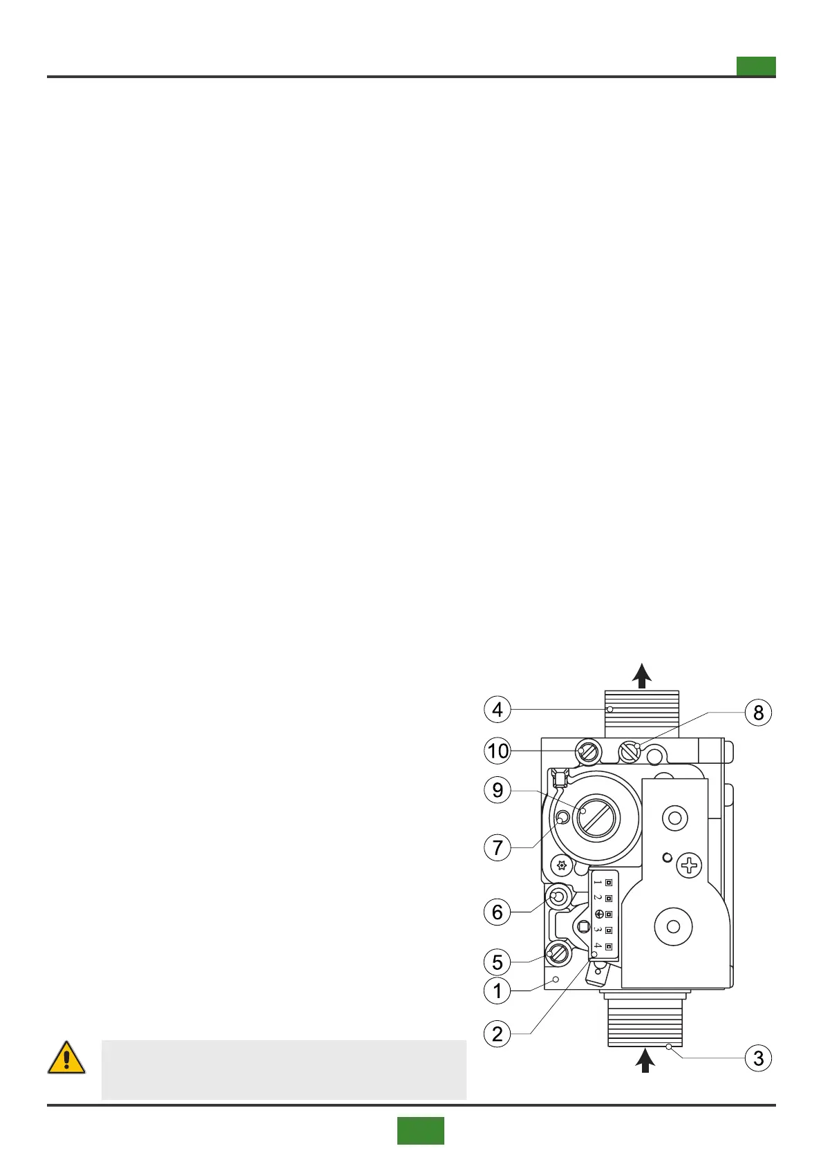
8.3.1 Adjustments on generators with 848 Sigma solenoid valve
(Eolo BC/BL 15÷65 RT)
1) Place the pressure gauge in point (6) of the gas valve to detect the gas pressure at the outlet
2) Use the ue gas analyzer to check that the combustion values are correct and correspond to table 8.6 on
page 92 (BC version) and table 8.8 on page 94 (BL version).
3) Make the adjustments in the order shown:
I) Remove the screw (9)
Fig. 8.1 Solenoid valve 848 Sigma
II) Oset adjustment by reducing the air signal to a mini-
mum (minimum fan speed allowed by the PWM) and
acting on the internal screw bringing the combustion
parameters to the required value. To increase the gas
pressure, tighten the screw.
III) Gas / air ratio adjustment by increasing the air signal
to the maximum (maximum fan speed allowed by the
PWM) and acting on the screw (8) to obtain the optimal
combustion value. To decrease the outlet gas pressu-
re, tighten the screw.
IV) Check zero by bringing the fan back to minimum speed
and check the combustion values, if necessary, adjust
the OFFSET again.
4) Final check of combustion.
5) Seal the screws (6) and (9).
WARNING
Seal the gas valve adjustment part after calibra-
tion.