39
4
SYSTEMA EOLO RT rev. 09ENIT04052021
ELECTRICAL CONNECTION
Please note
The devices equipped with the slave board mod. SCP674V202 can be managed through the
ground terminal mod. SCP674V122T and / or master SCM830 / SCM850.
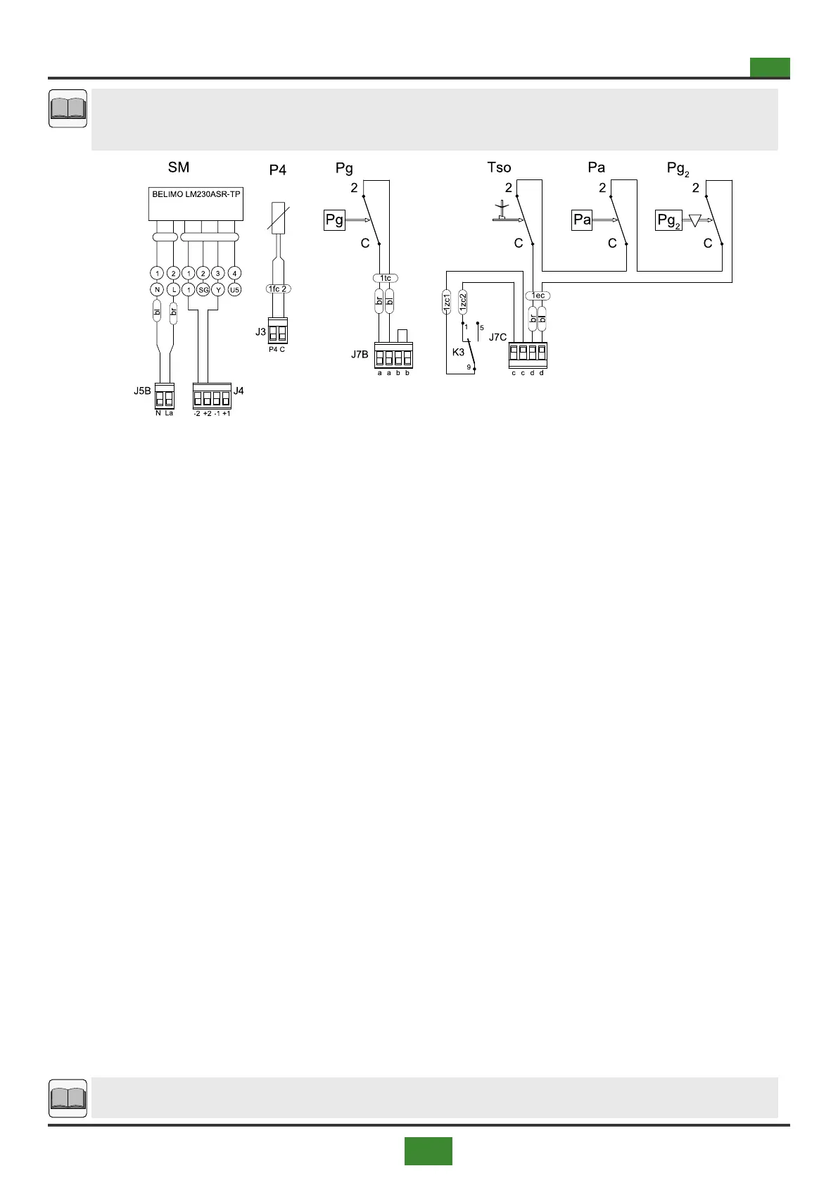
Connection to SCP674V030 motherboard and SCP674V202
slave board
Fig 4.9 Optional components for conguration with SCP674V202 slave board
Legend gs. 4.7, 4.8 and 4.9
ACC = Ignitor
Bp = Premix burner
Em = Ground electrode
EV = Solenoid valve
F1 = Fan protection fuse (J2A)
F2 = Fan protection fuse (J2B)
F3 = Burner protection fuse
F4 = Fuse burner protection
F5 = Fuse auxiliary protection J5B - J6B
F-M1 = Fan thermal protection
F-M2 = Second fan thermal protection
Hd = Display display with icons and symbols of
the burner status
Hd1 = Terminal grounded SCQT02G with built-in
probe
Hd2 = Terminaleaterrastandalone "touch" mod.
SCP674V122T
J = Telephone cable, maximum length 15 meters
J2 (SL1 / Hd1) = Connectors for connection via the cable (J)
of the ground terminal (mod. SCQT02G) with the
SLAVE board mod. SCP674V124 (SL1) on the ma-
chine
Ln = 4-pole line protected from interference, maximum len-
gth 15 ÷ 20 meters
K3 = Safety relays
K1-M1 = Fan contactor
K1-M2 = Second fan contactor
M3f-1 = Three-phase centrifugal fan motor
M3f-2 = Second three-phase centrifugal fan motor
P1 = Room probe for command and control with mains
THE2NET, and / or with the ground terminal mod(Hd2)
P2 = External probe for command and control with I2NET
network, and / or with the ground terminal SCP-
674V122T (Hd2)
P3 = Probe NTC 100 inlet air ow temperature
P4 = Second NTC 100 probe outlet air ow tempe-
rature (optional)
Pa = Pressure switch minimum air ow with manual reset
(optional)
Pg = Pressure switch minimum gas pressure (optional,
standard for models 120 ÷ 300)
Pg2 = Pressure switch maximum gas pressure with manual
reset (optional, standard for models 120 ÷ 300)
Pp = Button programming (KEY), to be connected only
when programming the board
RS485 = Serial cable for I²NET network for connection to the
SCM830 / SCM850 series earthed panel
SCP674V030 = Motherboard mod. SCP674V030 for command
and control of the appliance
SG = Disconnector general (see g. 4.1 on page 33)
SL1 = Slave card mod. SCP674V124 for connection of the
ground terminal mod. SCQT02G
SL3 = Slave card mod. SCP674V202 for connection to the
I²NET series earth panel or to the earth terminal - mod.
SCP674V122T (Hd2)
SM = Servomotor (optional) for appliances with external air
mixing
Sp = Micro switch for switching o the appliance in case of
opening the doors of the fan compartment
Sr = Reset button - normally open contact (neutral tro)
Tacc = Ignition transformer
Ts = Safety thermostat with automatic reset
Tso = Safety thermostat with manual reset (optional as an
alternative to Ts)
Vp = Premix burner fan
Xc = Flame control board housing
XG = Terminal block placed in the main switchboard hou-
sing panel (see g. 4.1 on page 33)
XS = Terminal block power supply line located in the bur-
ner compartment
XS2 = Terminal block placed in the burner housing com-
partment
Please note
For appliances with two fans see also g. 4.4 on page 36.