59
6
SYSTEMA EOLO RT rev. 09ENIT04052021
TUBAZIONE GAS
Important
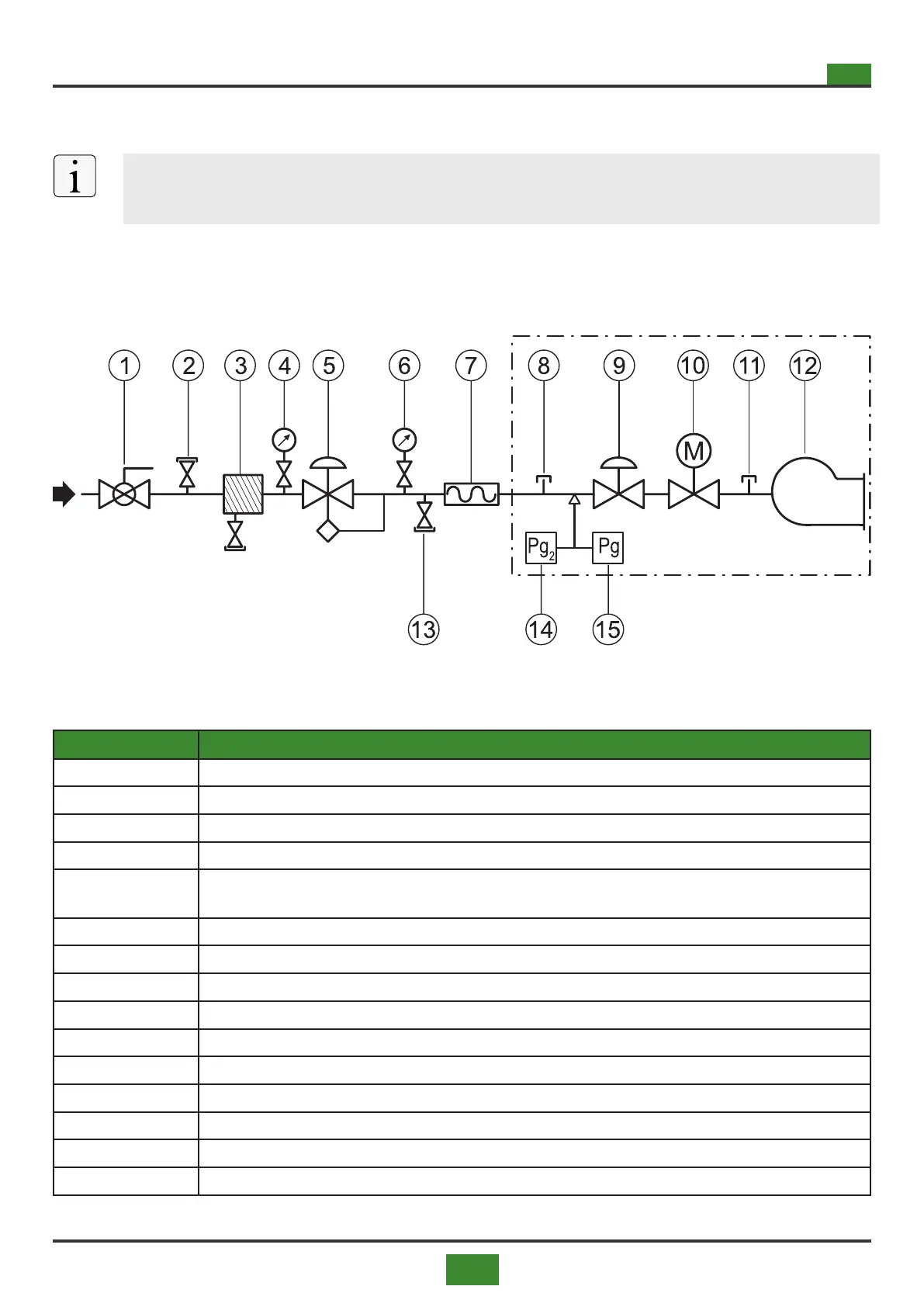
For methane supply with pressures higher than 20 mbar (200 mm ca), always provide a pres-
sure stabilizer for each appliance and adjust the pressure to 20 mbar.
Devices to be provided by the installer (1 ÷ 7, 13)
Devices supplied with the appliance (8 ÷ 12)
EOLO device
Fig. 6.1 Gas train
Tab 6.1 Gas train components
POS. DESCRIPTION
1 Manual gas shut-off ball valve
2 Gas pressure point upstream of the pressure regulator
3 Gas lter
4 Manometer upstream of the pressure regulator with push button cock
5
Gas pressure regulator with minimum and maximum pressure block device (outlet pressure = 0.04 bar) -
For inlet pressures <0.04 bar, provide a stabilizer
6 Manometer downstream of the pressure regulator with push button cock
7 Anti-vibration joint
8 Gas pressure socket placed at the inlet of the appliance's solenoid valve
9 Gas pressure regulator located on the appliance's solenoid valve
10 Safety solenoid valve
11 Gas pressure outlet located at the outlet of the appliance's solenoid valve
12 Burner
13 Ball valve with bleed
14
Maximum gas pressure switch with manual reset (40 mbar) - optional (standard for models 120 ÷ 300)
15
Minimum gas pressure switch (20 mbar) - optional (standard for models 120 ÷ 300)