12
| Installation
GB
5.6.2 Extract air, M5/ePM10 60% type filter
6 Installation
This section describes how to install the unit correctly. To ensure a proper and fail-free operation, it is important that
the unit is installed according to these instructions.
6.1 Unpacking
Verify that all ordered equipment are delivered before starting the installation. Any discrepancies from the ordered
equipment must be reported to the supplier of Systemair products.
6.2 Where/how to install
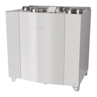
The SAVE VTR 700 should preferably be installed in a separate room (e.g. storeroom, laundry room or similar.).
When choosing the installation position, consideration must be taken that the unit requires regular maintenance. Leave
free space for opening of the front hatch in order to perform service and maintenance on components inside the unit.
The SAVE VTR 700 is supplied with approximately 2 m of power cable and fitted with a plug for 230V, single phase
earthed connection located at the bottom of the unit.
Recommended installation location for the outdoor air intake is the northern or eastern side of the building and with a
distance to openings for discharge of stale ventilation air, kitchen ventilator, central vacuum system, waste water drain-
age and other pollution sources like exhaust from traffic etc. Stale discharge air should ideally be led via a roof unit to
the outside and with a good distance to any outdoor air intake, windows etc.
6.3 Condensation drainage
In general no condensation drainage is needed for rotational heat exchangers at dry conditions. However, if a lot of hu-
mid air is present in the residence, a condensation drainage might be needed. Drainage connection is available as an ac-
cessory and can be ordered separately. Installation instructions for the drainage are enclosed in the drainage pipes
delivery.
Note:
The drainage connection is plugged in the bottom of the unit at delivery. To use the drainage: remove the
rubber seal and connect the drainage pipe. Connect the drainage pipe to the sewer. The water can not be
led straight to the sewer without a water trap.
211480 | B003

 Loading...