DE
Produktinformationen |
121
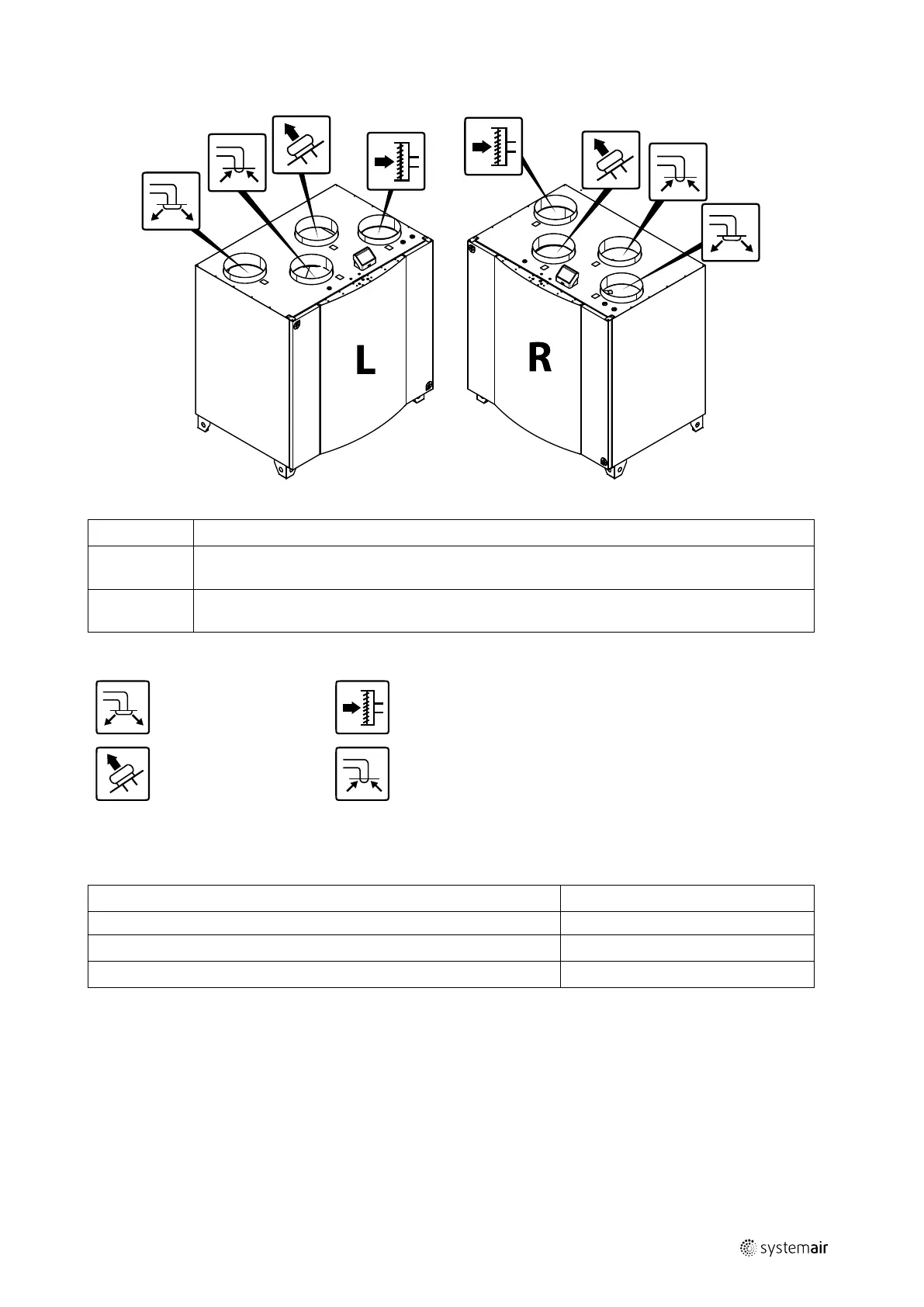
5.5.3 Kanalanschlüsse
Bild 3 Kanalanschlüsse
Position
Beschreibung
R
Rechtsseitiges Modell (der Zuluftanschluss befindet sich von vorne betrachtet auf der rechten Seite
des Gerätes)
L
Linksseitiges Modell (das Zuluftanschlussfeld befindet sich von vorne betrachtet auf der linken
Seite des Gerätes)
Symbol Beschreibung Symbol Beschreibung
Zuluft
Außenluft
Fortluft Abluft
5.5.4 Energieverbrauch und Absicherung
Nachheizregister
1670 W
Ventilatoren
336 W
Energieverbrauch, gesamt
2006 W
Sicherung
10 A
5.5.5 Platzbedarf
Um die Filter entfernen zu können (Abbildung 4), muss das Gerät so aufgebaut werden, dass vor ihm genügend Frei-
raum zur Verfügung steht, wie nachfolgend beschrieben.
2114802 | B003
 Loading...