14
| Electrical connections
GB
6 Connect the unit electrically to a main outlet using the
provided plug and check that it starts up correctly.
7 Electrical connections
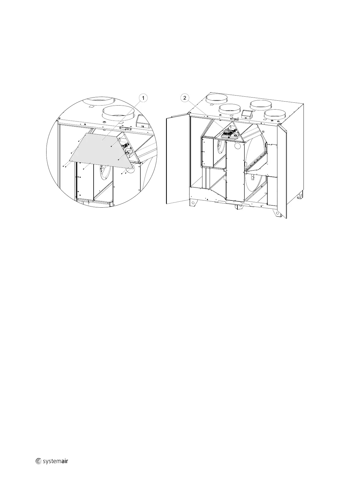
The SAVE VTR 700 is wired internally at factory.
The electrical connection box can be found behind a cover plate (pos. 1). The main circuit board (pos. 2) can easily be
taken out from the unit.
Fig. 6 Main circuit board position
7.1 Main board layout
The SAVE VTR 700 is equipped with built-in regulation and internal wiring.
The figure shows the main circuit board. See wiring diagram for more information.
211480 | B003
 Loading...