16
| Before starting the system
GB
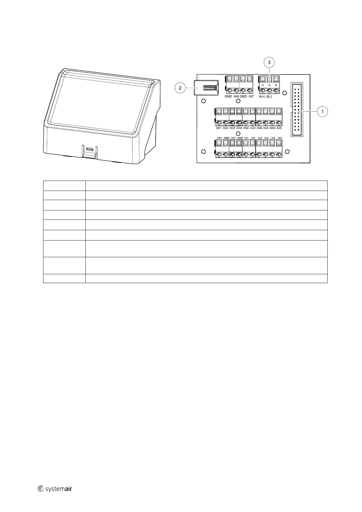
7.2 External connections (Connection board)
External connections to the main circuit board are done via connection board situated outside of the unit.
Fig. 8 External connection box and board
Position Description
1
Connection to the main circuit board
2
Connection for external control panel (HMI) or Internet access module (IAM)
3
Modbus RS485 connection
AI6–7
Freely configurable Analog input. None/Input type selection in HMI.
DO1–4
Freely configurable Digital output. None/Output type selection in HMI.
AO3–5
Freely configurable Analog output. None/Output type selection in HMI. Actuator type 0–10V, 10–
0V, 2–10V, 10–2V.
UI1–5
Freely configurable Universal input. Can be configured to act as Analogue input (0–10V) or as
Digital input (24V). None/Input type selection in HMI (NC or NO polarity).
24V Maximum current 200mA at 24VDC +-10%.
8 Before starting the system
When the installation is finished, check that:
• The unit is installed in accordance with the instructions
• The unit is correctly wired
• Outdoor and exhaust air dampers and silencers are installed and that the duct system is correctly connected to the
unit
• All ducts are sufficiently insulated and installed according to local rules and regulations
• Outdoor air intake is positioned with sufficient distance to pollution sources (kitchen ventilator exhaust, central vac-
uum system exhaust or similar)
• All external equipment are connected
• The unit is correctly configured and commissioned
• The week schedule and airflow settings are correctly programmed.
9 Configuration
9.1 General
SAVE VTR 700 has a modern touchscreen LCD control panel, simply known as HMI — Human Machine Interface. The
touchscreen display provides information about current state of the unit and allows you to control all system functions.
Settings are done by touching the icons or options. The touch screen is sensitive and it is not necessary to press too
hard.
211480 | B003
 Loading...