54
|
Accessories GB
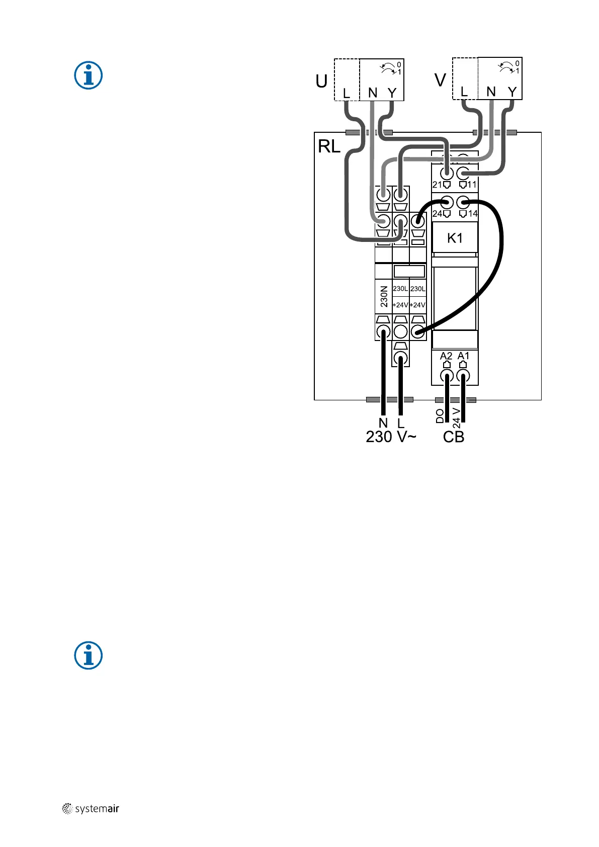
Fig. 1 Damper connection
Note:
24 VAC dampers can be powered and
controlled only by using a relay mounting kit
with a transformer (article number: 153548).
This installation procedure describes how to connect
dampers powered by 230 V~ with a relay mounting kit
without transformer (article number: 153549).
Installation and connection
1. Install dampers (U/V).
2. Connect control signal wires (24V, DO) coming out from
the relay box (RL) to any free digital output on the con-
nection board (CB).
3. Connect power supply wires (N) from dampers to the
terminal block. Connect control signal wires (Y, line)
from dampers to relay socket terminals (11, 21). See
illustration.
When damper with a non-spring return actuator is
used, an addition power line (L) has to be connected to
the terminal block since such damper requires constant
power supply.
4. Connect power supply wires (L, N) coming out from the
relay box to 230 V~ power source.
Configuration
1. Go to Service menu
2. Enter password (default 1111)
3. Configure control signal to the relay. Go to Output menu. Select DIGITAL tab. Select the digital output to which the
relay is connected. Example if it is connected to DO3 on the connection board, then select DIGITAL OUTPUT 3 and
select signal type as Outdoor-/Exhaust Air Damper from the output type list.
11.5.2 Multiple control panels
Multiple control panels (up to 10) can be connected to one unit with the help of diverting plugs. A single diverting plug
allows to connect two control panels. A diverting plug can be connected to another diverting plug to further increase
the number of control panels that can be connected simultaneously.
Note:
• If the 24 V power supply on the connection board (CB) is used for other equipment, the number of control
panels that can be powered from the unit will decrease.
• A single active control panel draws 50 mA. The connection board supplies up to 250 mA. If no other
accessories use 24 V power supply from the unit, up to 5 control panels can be connected without a need
of external power supply. In order to connect more than 5 control panels, an external power supply is
required.
Control panel is available in black or white colour.
211480 | B003
 Loading...