GB Service
|
37
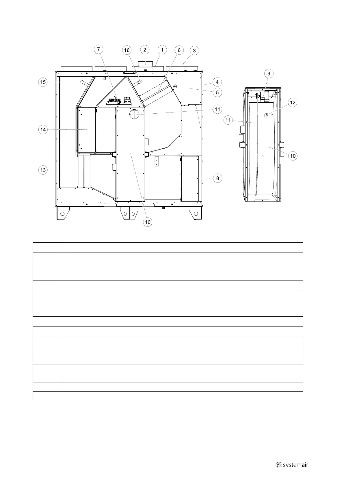
10.2 Internal Components
Fig. 12 Components
Position Description
1
Relative humidity sensor
2
External connections
3
Supply air sensor
4
Overheat protection sensor
5
Internal electrical re-heater
6
Extract air filter
7
Main circuit board
8
Supply air fan
9
Rotor motor and belt pulley
10
Rotating heat exchanger
11
Heat exchanger drive belt
12 Rotor sensor
13
Supply air filter
14
Extract air fan
15
Outdoor air sensor
16 Extract air sensor
10.2.1 Description of Components
10.2.1.1 Fans
Fans have an external EC type rotor which can be steplessly controlled individually 16–100%. The motor bearings are
life time lubricated and maintenance free. It is possible to remove the fans for cleaning, see “User Manual” for more
information.
211480 | B003
 Loading...