GB Accessories
|
51
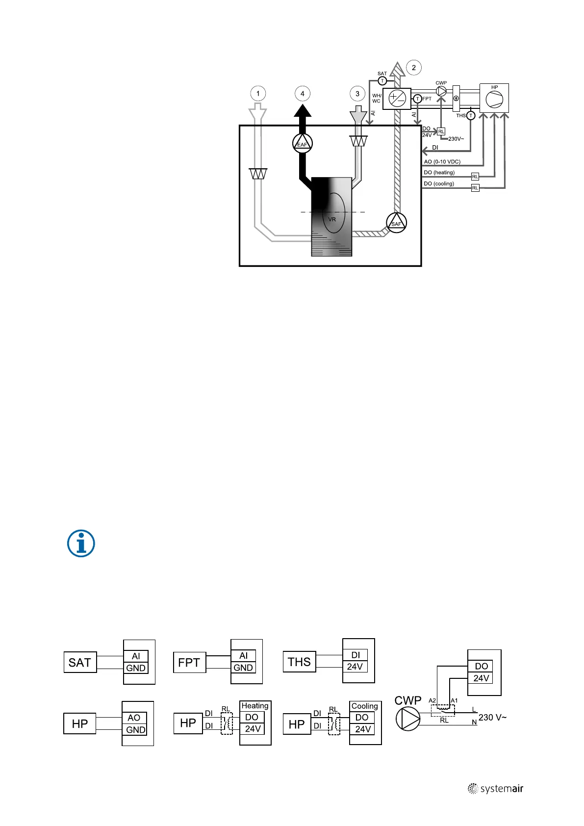
• WH/WC — change-over coil
• FPT — frost protection sensor
(optional)
• SAT — supply air temperature sensor
• THS — thermostat for sensing if the
temperature of heating/cooling fluid
in the system is right (optional)
• HP — heat pump (or other device for
heating and cooling)
• CWP — water pump
• RL — relay
• 1 — Outdoor air
• 2 — Supply air
• 3 — Extract air
• 4 — Exhaust air
Component/product — Article number:
• Duct sensor -30-70C (SAT) — 211524
• Surface sensor -30-150C (FPT) — 211523
• Relay 24V with socket — 211248
Installation and connection
1. Install change–over coil in the duct. Install a water pump if necessary. The turning on and off of water pump should
be controlled with a relay (RL). Connect the relay to any free digital output and 24 V on the connection board. Then
connect the power supply and a water pump (CWP) to the relay.
2. Connect a control signal wire (if available) of the heat pump (HP) to any free digital output and 24 V on the connec-
tion board.
3. Connect cooling and heating start signal wires to any free digital outputs on the connection box. Relays (RL) must be
used.
4. The frost protection sensor (FPT) should be strapped on a surface on the return water pipe. Connect the frost protec-
tion sensor (FPT) sensor to any free analog input.
5. An internal supply air temperature sensor (SAT, default connection AI2 on the main circuit board) must be replaced
by a duct temperature sensor which can be acquired as an accessory. A duct temperature sensor must be installed in
the duct after heater/cooler. Connect the duct temperature sensor to analog input 2 (AI2) replacing the internal sup-
ply air temperature sensor.
Note:
A duct temperature sensor can be connected to analog inputs 6–7 on the connection board for better
access and then configured as a supply air temperature sensor. However the internal supply air
temperature sensor must be disabled in the control panel first.
6. A thermostat can be used to send signals (change-over feedback) regarding which actual medium (hot or cold) is
currently in a pipe. This signal can be also sent directly from the heat pump if such function is available. If heating is
demanded but only cold water/refrigerant is available - heating is deactivated).
Connect a change-over feedback wire (THS) to any free digital input and 24 V on the connection board.
Fig. 19 Change-over heating/cooling connections
211480 | B003
 Loading...