TB7100 Installation and Operation Manual Preparation for Operation 111
© Tait Electronics Limited December 2005
Receiver
Digital IO
The user-defined settings for the receiver digital IO are shown below.
The cells in grey denote mandatory settings.
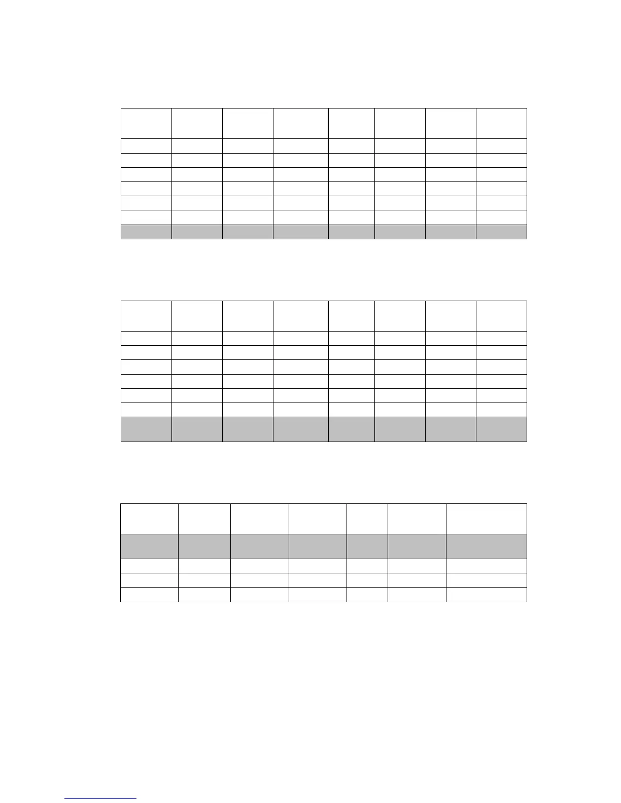
Transmitter
Digital IO
The user-defined settings for the transmitter digital IO are shown below.
The cells in grey denote mandatory settings.
Receiver Audio The user-defined settings for the receiver audio IO are shown below.
The cells in grey denote mandatory settings.
Pin Direction Label Action Active Debounce
Signal
State
Mirrored
To
AUX_GPI1 Input BIN_0 BCD_Pin_0 Low 10 None None
AUX_GPI2 Input BIN_1 BCD_Pin_1 Low 10 None None
AUX_GPI3 Input BIN_2 BCD_Pin_2 Low 10 None None
AUX_GPIO4 Input BIN_4 BCD_Pin_3 Low 10 None None
AUX_GPIO5 None RX_DO_1 No Action Low None None None
AUX_GPIO6 None RX_DO_2 No Action Low None None None
AUX_GPIO7 Output RXGATE Busy Status High None None None
Pin Direction Label Action Active Debounce
Signal
State
Mirrored
To
AUX_GPI1 Input BIN_0 BCD_Pin_0 Low 10 None None
AUX_GPI2 Input BIN_1 BCD_Pin_1 Low 10 None None
AUX_GPI3 Input BIN_2 BCD_Pin_2 Low 10 None None
AUX_GPIO4 Input BIN_4 BCD_Pin_3 Low 10 None None
AUX_GPIO5 None TX_DO_1 No Action Low None None None
AUX_GPIO6 None TX_DO_2 No Action Low None None None
AUX_GPIO7 Input TXKEY External PTT
1
High 2 None None
Rx/PTT Type Tap In Tap In Type
Tap In
Unmute
Tap Out
Tap Out
Type
Tap Out Unmute
Rx None A-Bypass In On PTT R4 D-Split Busy detect +
Subaud
Mic PTT None A-Bypass In On PTT None C-Bypass Out On PTT
EPTT1 None A-Bypass In On PTT None C-Bypass Out On PTT
EPTT2 None A-Bypass In On PTT None C-Bypass Out On PTT

 Loading...


