ELECTRICAL TROUBLESHOOTING
SECTION 4 Main Sequence PAGE 12
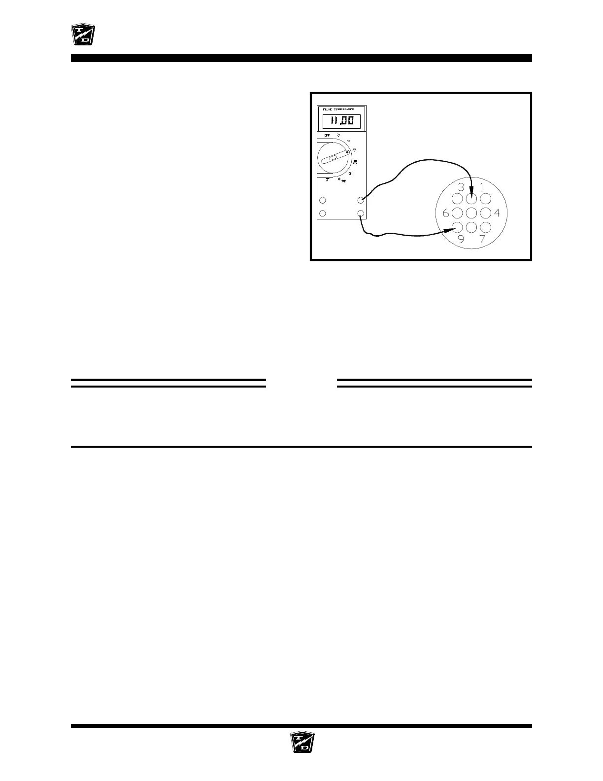
Connect a voltmeter between pin #9 (-) and pin
#2 (+) in the test harness.
Depress the accelerator pedal to engage
MS-1 only.
•
If the voltage is between 6.0 and 6.5 volts
and the test at the PMC #2 terminal in
the Control Wire Input section failed then
the wire or interlock switches between
the accelerator module pin #2 and the
PMC pin #2 is open. Stop trouble
shooting here and repair the problem.
When the repair is completed,
completely retest the vehicle before
lowering the drive wheels to the ground.
•
If the voltage is not between 6.0 and 6.5
volts then the accelerator module has failed. Stop trouble shooting here and repair the
problem. When the repair is completed, completely retest the vehicle before lowering the
drive wheels to the ground.
Now Depress the accelerator module fully.
•
If the voltage is not between 11.0 and 11.5 volts then the accelerator module has failed.
Stop trouble shooting here and repair the problem. When the repair is completed,
completely retest the vehicle before lowering the drive wheels to the ground.
+
-
The voltage shown is for illustration
only. The actual voltage may vary.
STOP
Stop, do not continue. If you reached this point without a solution, then you may have an
unanticipated problem or have made an error during testing. It is important to review the
trouble shooting steps that have led to this point. The tests may need to be repeated.