ELECTRICAL TROUBLESHOOTING
SECTION 4 Main Sequence PAGE 16
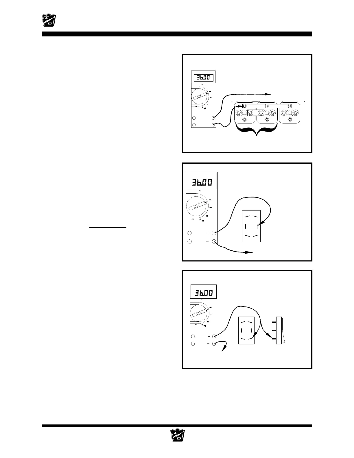
Connect a voltmeter across the Solenoid
Negative Buss Bar and battery positive.
NOTE: You may skip this test if it was
completed in a previous section
•
If the voltage is not at battery volts then
check the wiring to battery negative and
the negative circuit breaker. Stop trouble
shooting here and repair the problem.
When the repair is completed,
completely retest the vehicle before
lowering the drive wheels to the ground.
Connect a voltmeter across the center terminal
of the forward and reverse side of the F&R switch
and battery negative.
Close all interlock switches, turn the Key
Switch ON, and place the F&R Switch in
Forward.
Depress the accelerator pedal fully.
•
If the voltage is not at battery volts then
go to the
Accelerator
sequence.
Connect a voltmeter across the forward terminal
of the forward and reverse side of the F&R switch
and battery negative.
Close all interlock switches, turn the Key
Switch ON, and place the F&R Switch in
forward.
Depress the accelerator pedal fully.
•
If the voltage is not at battery volts then
the F&R switch has failed. Stop trouble
shooting here and repair the problem.
When the repair is completed,
completely retest the vehicle before
lowering the drive wheels to the ground.
ISO
FWD/REV
Solenoids are shown for reference only.
The type of solenoid in your truck may
look different
Main Battery
Positive
The voltage shown is for illustration
only. The actual voltage may vary.
A
OFF
FLUKE 79
-
+
SERIES II MULTIMETER
Hz
V
mV
V
The CENTER terminal is the
Green/Black wire
Battery Negative
A
OFF
mV
V
V
Hz
FLUKE 79
SERIES II MULTIMETER
The FORWARD terminal is
diagonally opposite the forward side
of the rocker on the switch
Battery Negative
A
OFF
mV
V
V
Hz
FLUKE 79
SERIES II MULTIMETER
F&R switch seen
from the rear
F&R switch seen from
the side depressed in
the FORWARD gear