CONFIG. M5000
M5CONFIG
Rev 1.2 Page 6
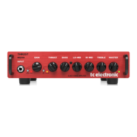
Dip 1 Dip 2 Dip 3 Dip 4 Addr.
1. DSP off off off off 0
2. DSP off on off off 2
3. DSP off off on off 4
4. DSP off on on off 6
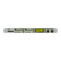
Dip 1 Dip 2 Dip 3 Dip 4 Addr.
1. ADDA on off off off 1
2. ADDA on on off off 3
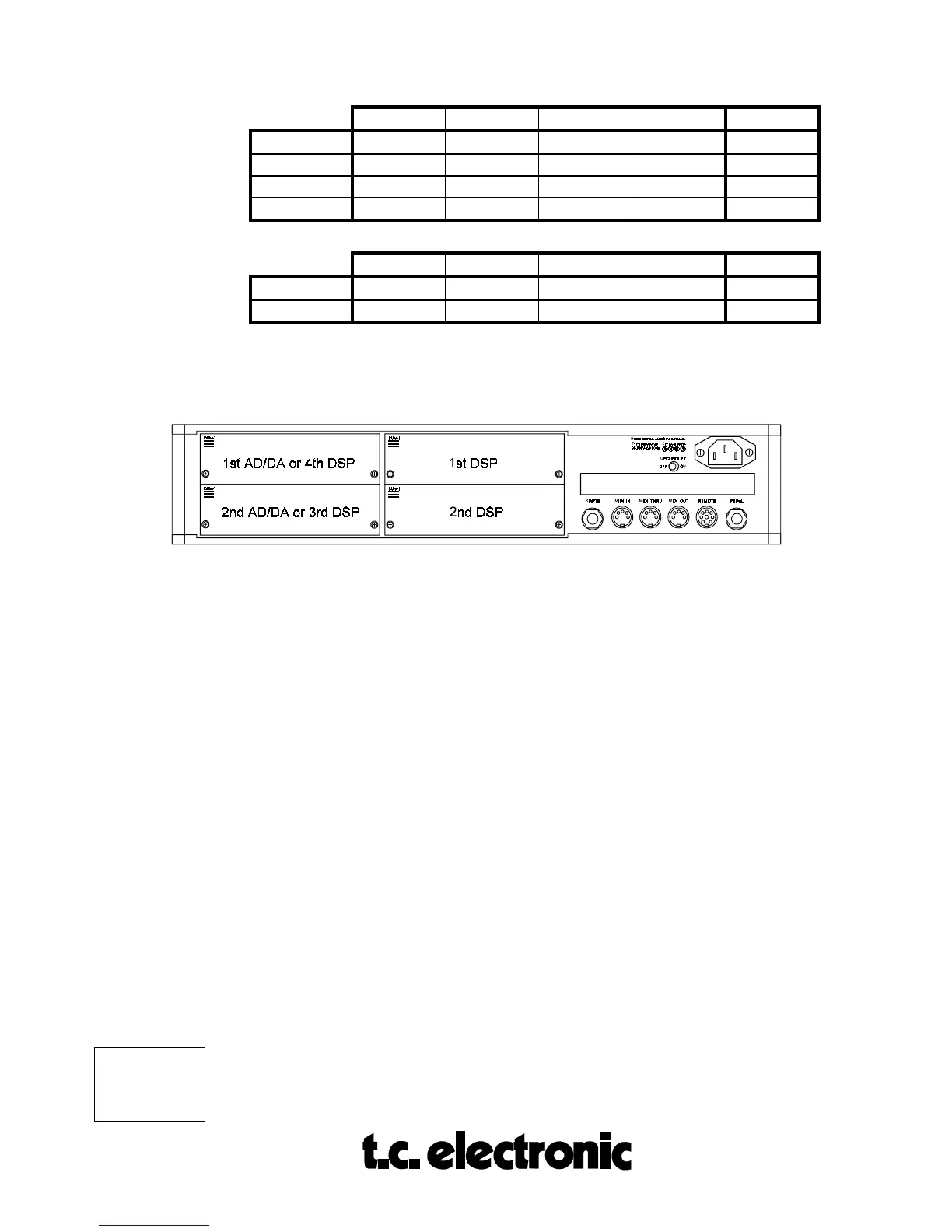
4. Insert the module as shown in figure 1 below.
fig. 1
AD/DA cards are always mounted as far away as possible from the power supply!
The module cards will fit in the module guides inside the M5000 frame.
It is
important that the modules are mounted correctly in these blue guides
to ensure
proper connection to the buss. It is recommended that you use a powerful light source
in order to see properly inside the frame. Improper connection may cause serious
damage to the modules.
5. Fasten the module with the two screws and connect the cables.
6. The module cards will be initialized during the next power up.
7. If there are problems e.g. the cards are not recognized by the M5000 frame,
please check once again - especially the address settings.
In Appendix C you can find a self-test procedure to see if the M5000 has found
the cards at the proper addresses and if the M5000 is working alright.
 Loading...