3-47
Fig. 3.161
Fig. 3.160
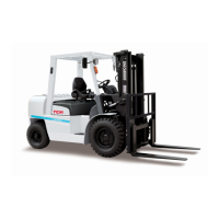
③ Install the drive pinion assembly (1) on the
housing along with two 0.5-mm [0.02 in.]
shims (2). Tighten only two bolts which are
located diagonally.
④ Install the cross case assembly on the housing
andlightlytightenthecapttingnuts.Install
the two adjustment nuts.
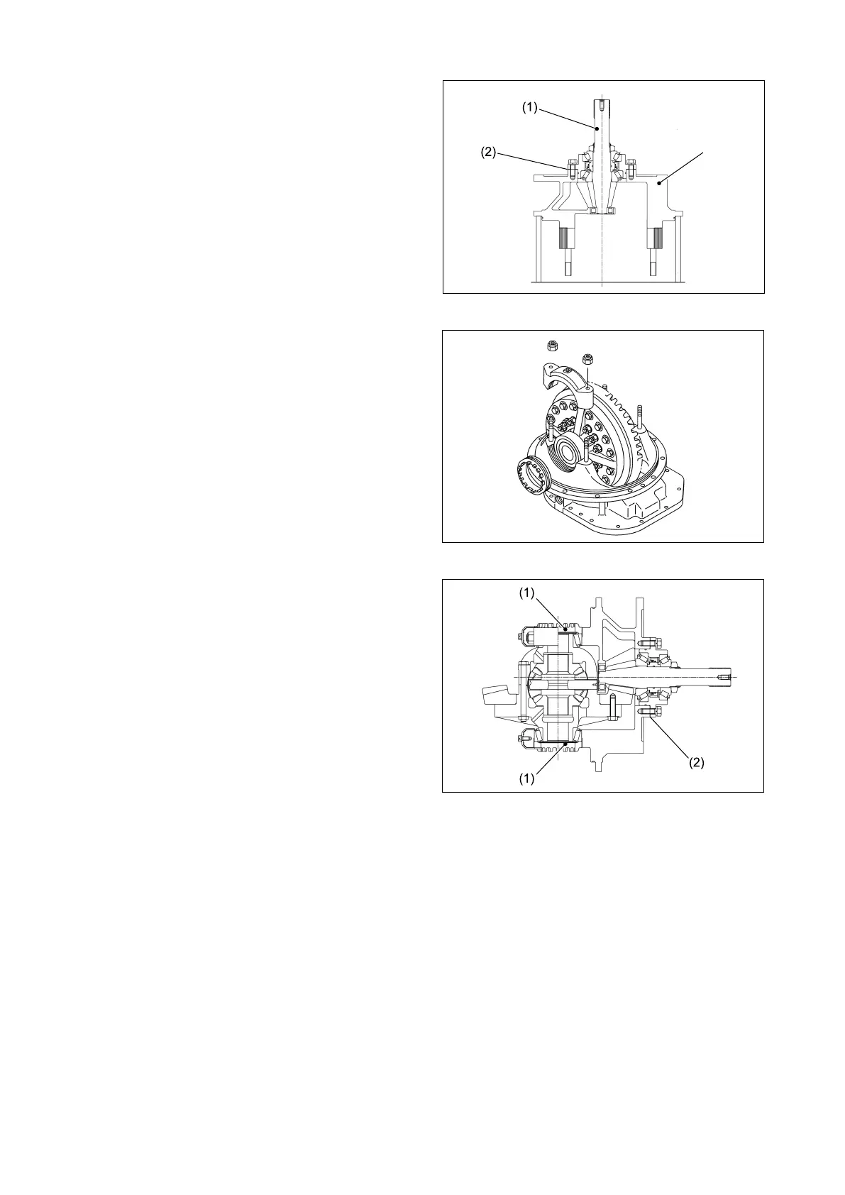
⑤ Adjusting backlash and engagement
When the ring gear requires moving, loosen
the adjustment nuts (1) and move the ring
gear. For the drive pinion, increase or reduce
the number of bearing cage shims (2).
For the adjustment procedure, see Table 3.1.
Backlash: 0.23 to 0.33 mm [0.009 to 0.013 in.]
Fig. 3.159
CARRIER
 Loading...