3-60
Fig. 3.201
Fig. 3.200
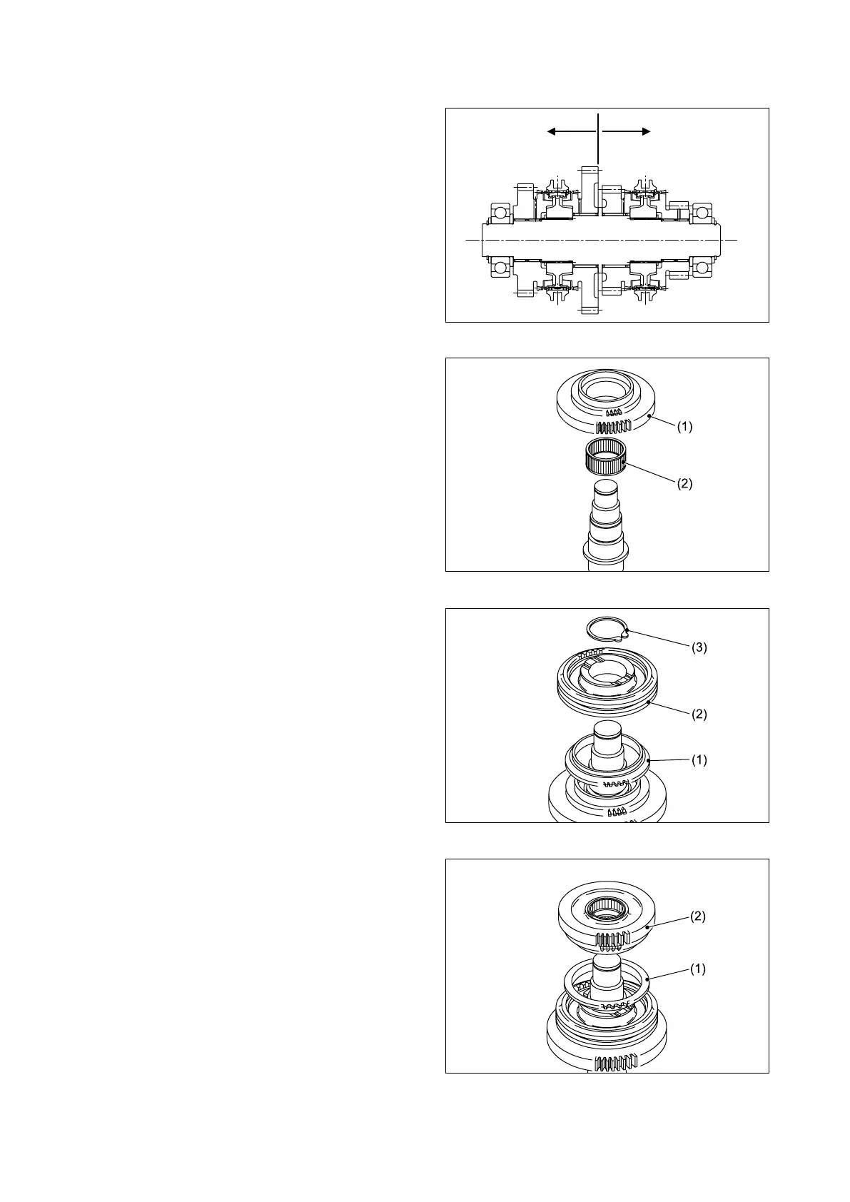
Fig. 3.199
■REASSEMBLING MAIN SHAFT
The reassembly procedure for the 1st/2nd speed
side of the main shaft will be explained in this
section. The fwd/rev and 1st/2nd speed sides of the
main shaft are similar and therefore this reassembly
procedure pertains to both.
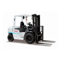
Understand the direction and position of the
component parts on the main shaft by referring to
Figure 3.198.
① Install the low gear (1) and needle bearing
(2) onto the end of the main shaft that has the
smaller chamfer.
② In st all the blo ck r in g (1 ). In st al l the
synchronizer (2) on the splines of the main
shaft, and secure with the snap ring (3).
③ Install the block ring (1) and high gear (2)
(with needle spring).
Fig. 3.198
1st/2nd speed side
Fwd/rev side