3-95
Fig. 3.300
Fig. 3.303
Fig. 3.302
Fig. 3.301
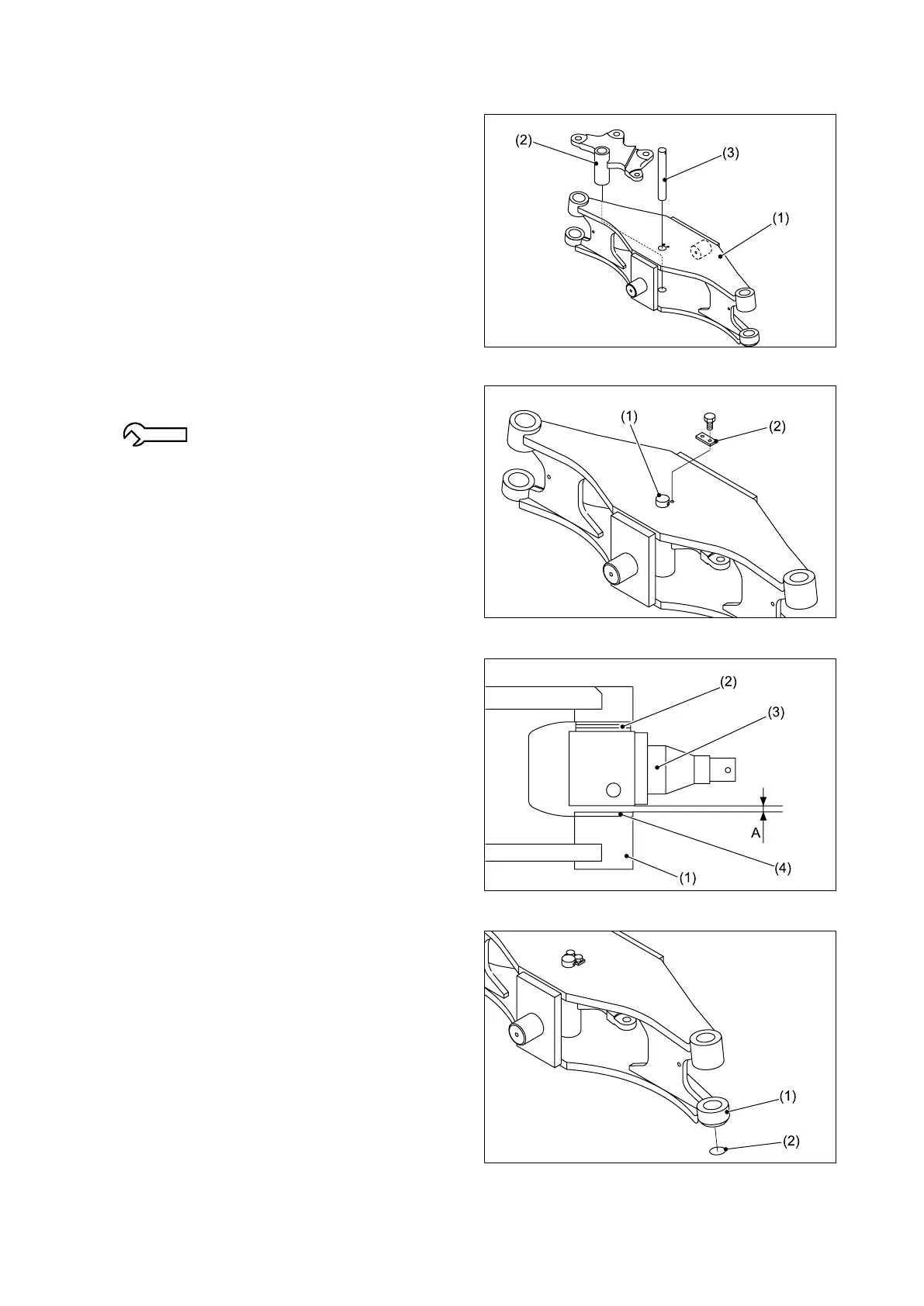
■REASSEMBLY
① Install the center arm (2) on the steering axle
(1) using the center arm pin (3).
② Install the lock plate (2) on the center arm pin
(1).
7.8 - 11.7 N-m {0.8 - 1.2 kgf-m}
[5.8 - 8.6 lbf-ft]
③ Select appropriate shims as follows:
Place the thrust bearing (2) and knuckle (3)
between the bosses of the steering axle (1).
Select shims (4) of correct thickness to
provide a clearance of 0.5 mm [0.02 in.] at
“A”.
④ Install the “O”-ring (2) to the bottom of the
lower boss (1) of the steering axle.
Note: Use a new “O”-ring.