3-109
Fig. 3.351
Fig. 3.354
Fig. 3.353
Fig. 3.352
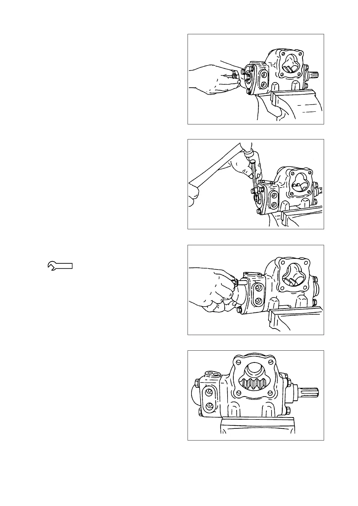
⑧ Install the lock nut as follows. With the
worm shaft turned fully counterclockwise,
finger-tighten the lock nut until there is no
play in the thrust bearing. Mark the lock nut
to identify the position of the groove in the
worm shaft. Then loosen the lock nut and
makeitngertightagain.Checktomakesure
if the position of the mark has not changed. If
it is unchanged, tighten the lock nut about 5
degrees further.
●Startingtorque: 0.98N-m{10kgf-cm}
[0.72 lbf-ft] or less
⑨ Stake the lock nut.
⑩ Install the “O”-ring in the end cover groove
and install the end cover.
37.3 - 56.9 N-m {380 - 580 kgf-cm}
[27.51 - 41.97 lbf-ft]
⑪ Align the center of the rack gear in the ball
nut with the center of the opening where the
side cover will be installed.