3-110
Fig. 3.355
Fig. 3.357
Fig. 3.356
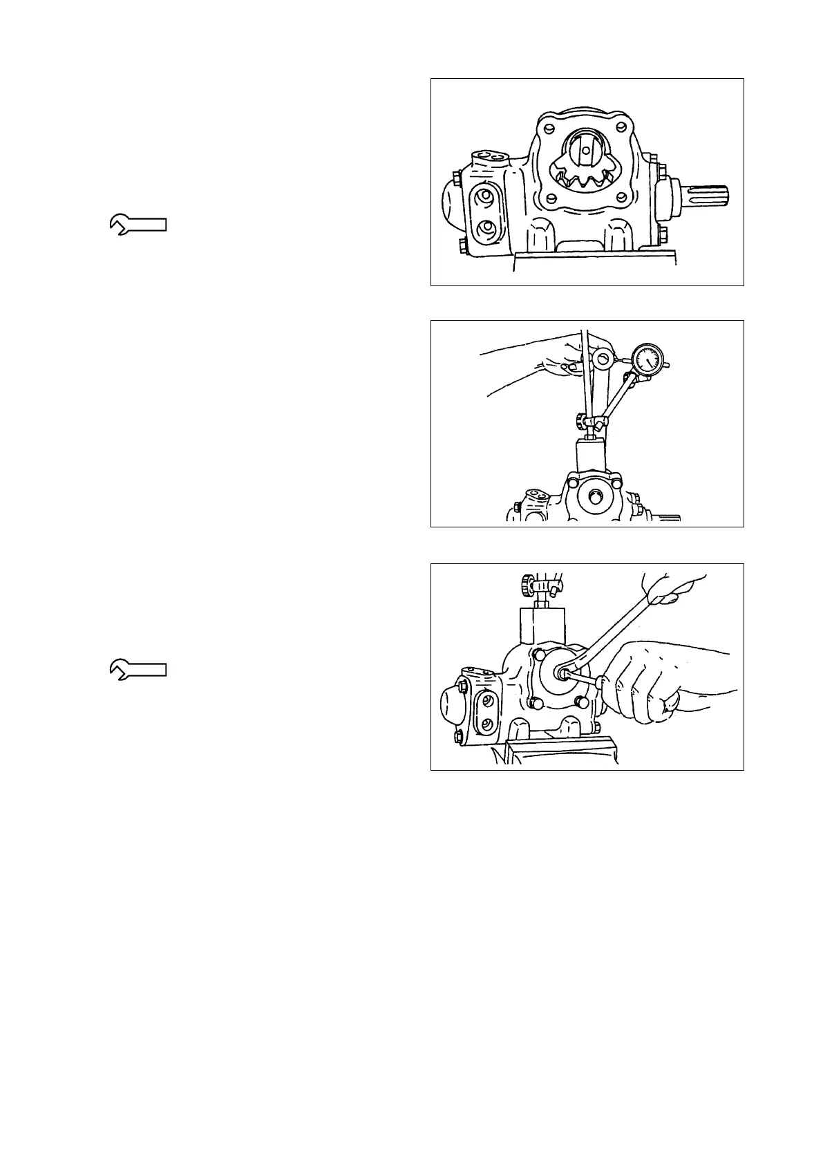
⑫ Install the sector shaft in the gear case. Install
the adjustment screw and shims in the sector
shaft groove. Install the “O”-ring in the
groove in the side cover. Align the screw hole
in the side cover with the adjustment screw.
Then install the side cover by turning the
adjustment screw.
34.3 - 53.0 N-m {350 - 540 kgf-cm}
[25.3 - 39.1 lbt-ft]
⑬ Install the pitman arm in the middle of the
worm shaft range of movement. Next, place
a dial gauge 150 mm [5.906 in.] away from
the center of the pitman arm. Measure any
looseness in the pitman arm.
●Tolerance:lessthan0.3mm[0.012in.]
If the measured looseness is greater than 0.3
mm [0.012 in.], adjust it using the adjustment
screw. After making any needed adjustment,
install the packing and secure with the lock
nut. Then install the packing and the cap nut.
19.6 - 29.4 N-m {200 - 300 kgf-cm}
[14.5 - 21.7 lbf-ft]
⑭ Turn the worm shaft and count the total
number of turns to the end.
●Totalnumberofturns:4-2/3
⑮ Turn the worm shaft fully clockwise or
counterclockwise until it reaches the stop.
Release the worm shaft and it should turn
back about 50 degrees smoothly by itself.