3-124
Fig. 3.400
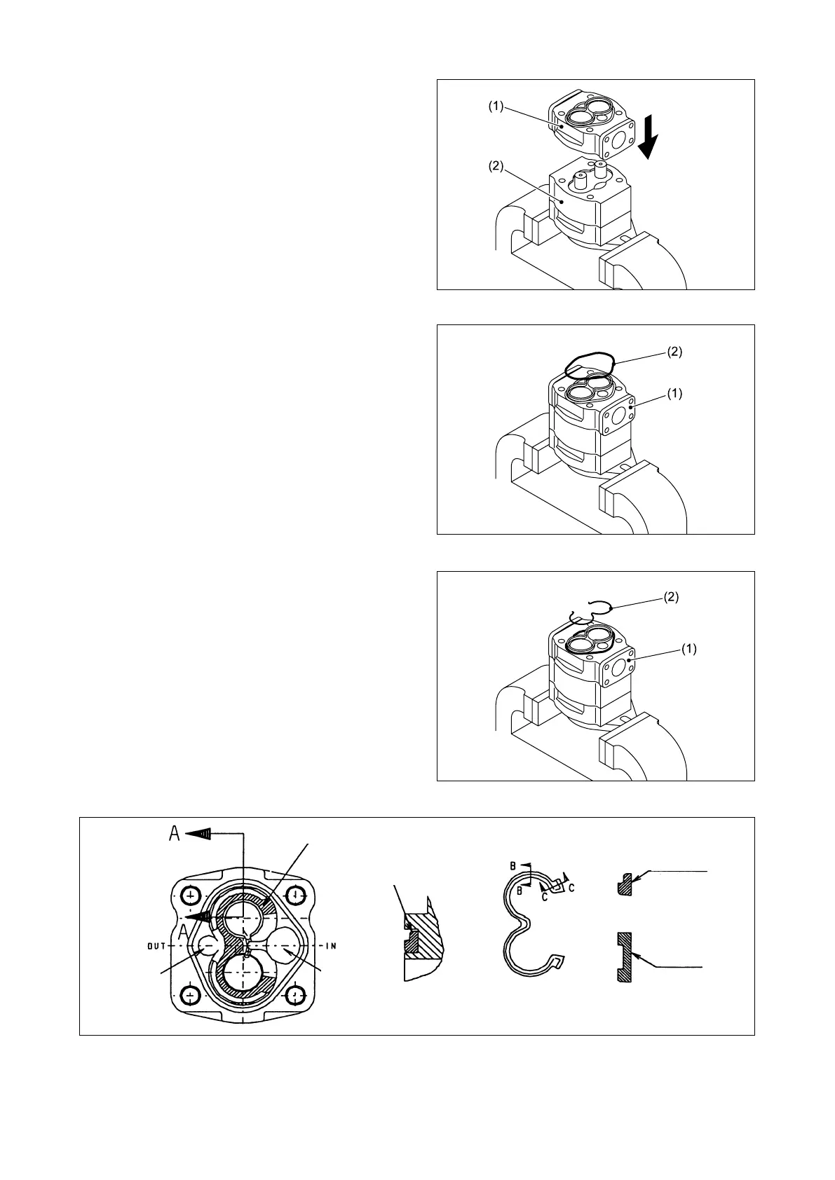
Fig. 3.403
Fig. 3.402
Fig. 3.401
⑪ Install the adapter (1) in the pump body half 1
(2) with its gasket pointed downward.
⑫ Install a new gasket (2) in the groove in the
adapter (1).
Note: Use caution not to twist the gasket.
⑬ Install a new “E” gasket (2) in the groove in
the adapter (1), referring to Fig. 3.403.
“E” gasket groove
Discharge
side
Suction
side
The “E” gasket should
be installed with its at
surface pointing to the
bottom of the groove.
C-C section
A-A section
(b) “E” gasket
Discharge
side
Suction
side
B-B section
Flat surface
Flat surface