3-123
Fig. 3.396
Fig. 3.399
Fig. 3.398
Fig. 3.397
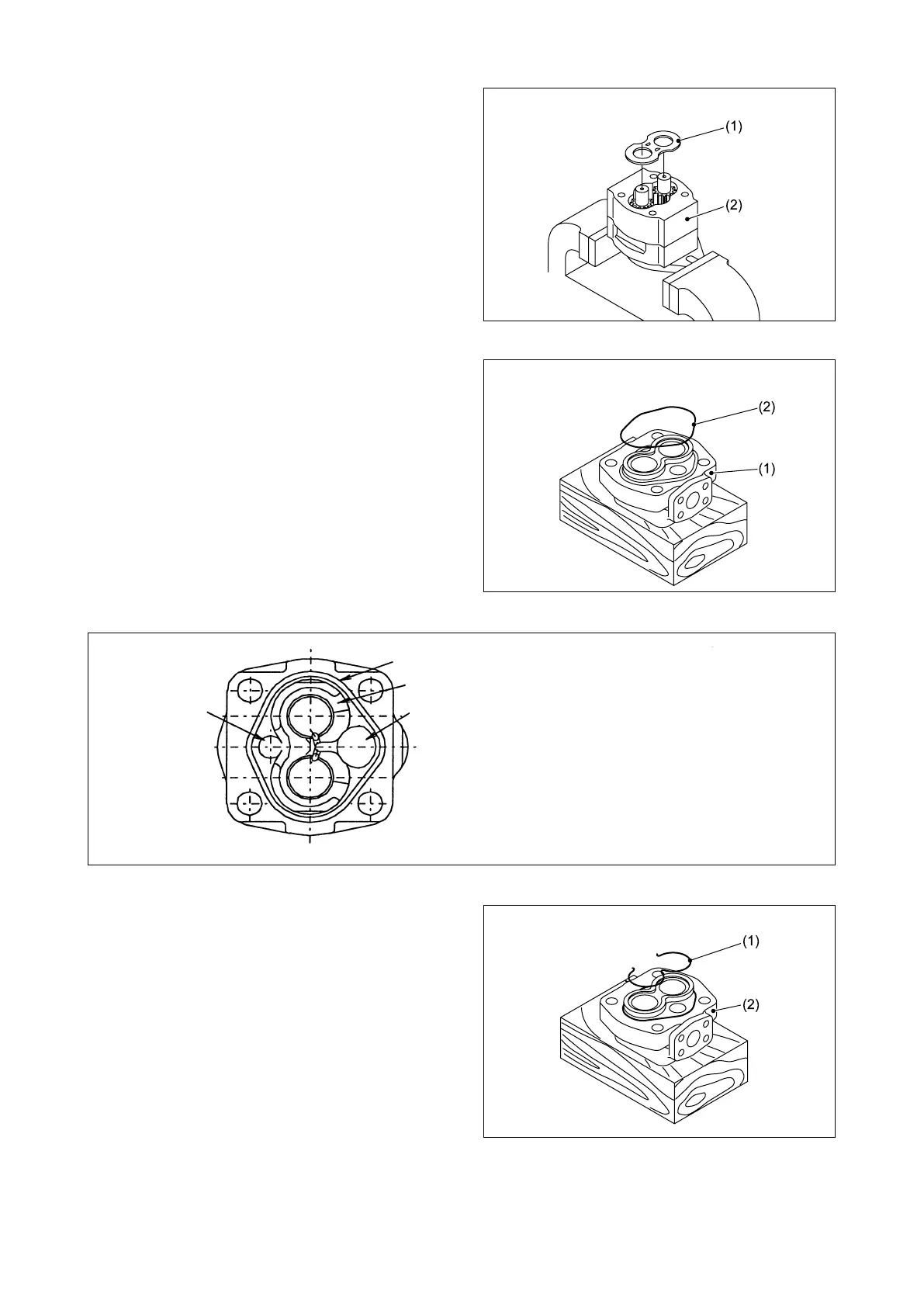
⑧ Install the adapter side plate (1) in the pump
body half 1 (2), as shown in Fig. 3.392.
⑨ Apply grease on a new gasket (2) in some
points and install the gasket (2) in the adapter
(1) groove.
⑩ Install the “E” gasket (1) on the adapter (2), as
shown in Fig. 3.388.
Gasket groove
“E” gasket
Suction sideDischarge side
The adapter is commonly used for the “L”
(counterclockwise rotation) type and the “R”
(clockwise rotation) type. Align the discharge
side with the suction side.