3-122
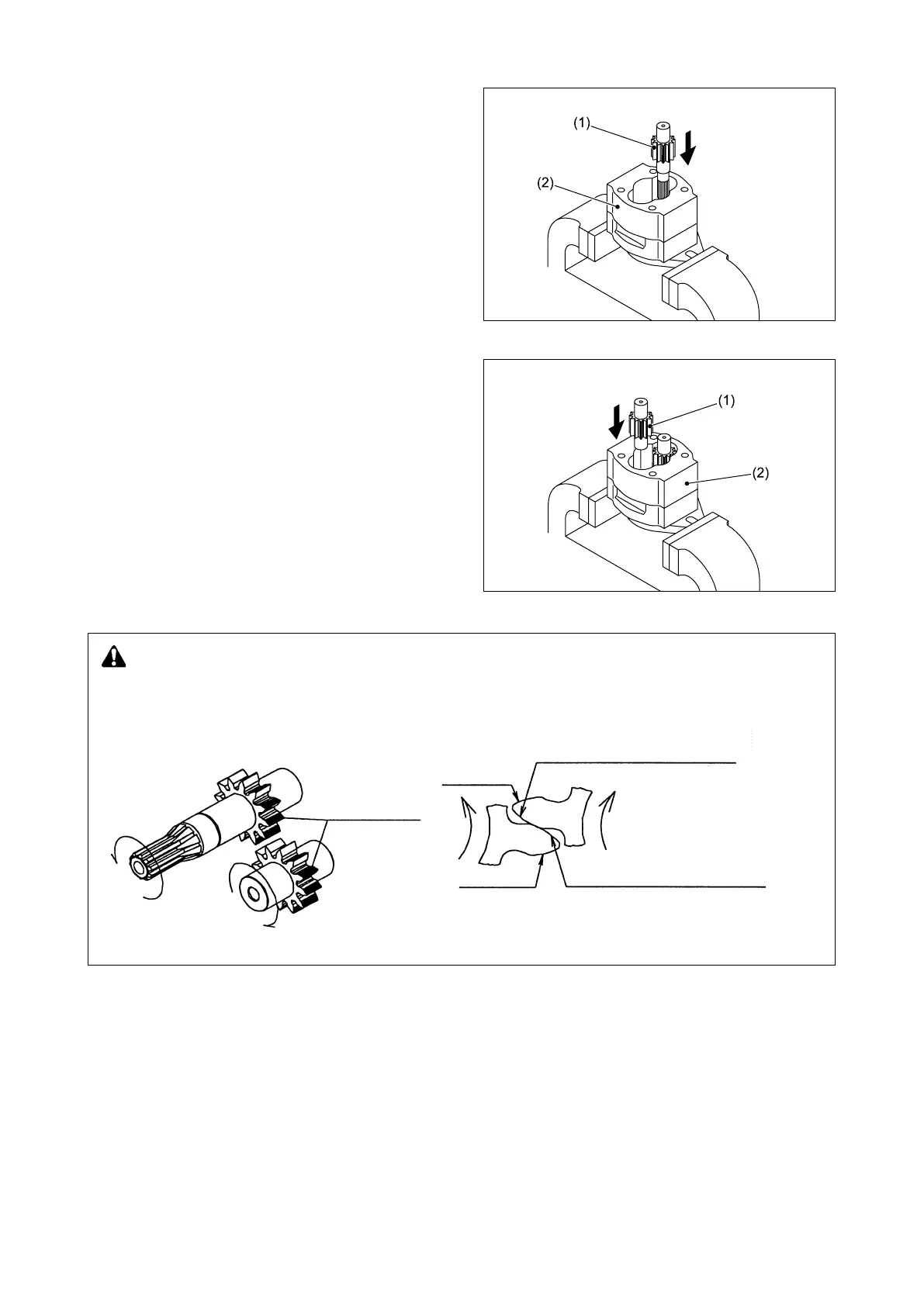
Fig. 3.393
Fig. 3.395
Fig. 3.394
⑥ Install the drive gear (1) in the pump body
half 1 (2), with its splines pointed downward.
⑦ Install the driven gear (1) in the pump body
half 1 (2), as shown in Fig. 3.395.
CAUTION
The sketch shows the engagement of an L-shaped pump. Since the tooth proles of the two gears
are asymmetric, install them with their larger pressure angle sides pointed to each other. Failure to
do so might damage the gear teeth.
Greater pressure angle side
(driven-side engagement surface)
Greater pressure angle side
(drive-side engagement surface)
Smaller pressure angle aide
(b) Engagement of asymmetric tooth proles
Smaller pressure
angle side
Engagement surfaces
(shaded sections)
(a) Engagement of 1st pump
Drive side
Driven side