3-121
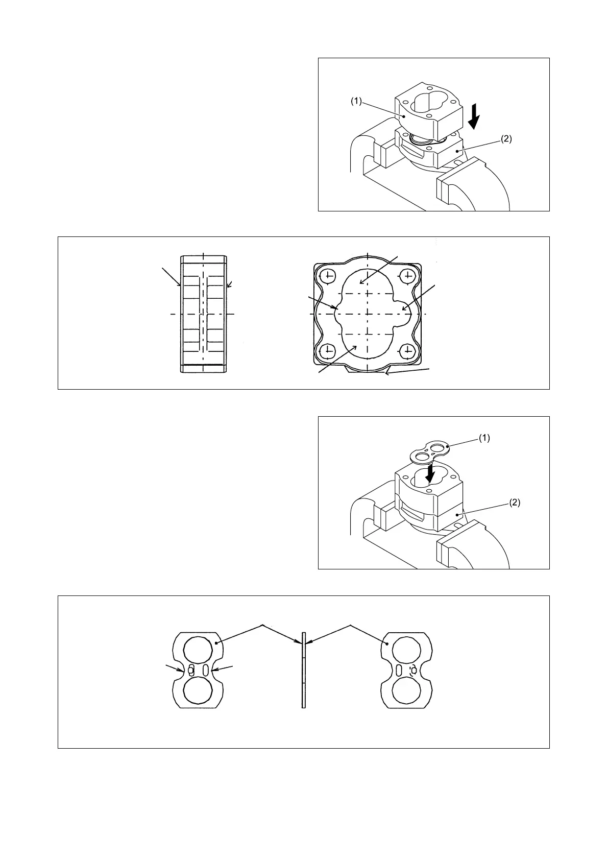
Fig. 3.389
Fig. 3.392
Fig. 3.391
Fig. 3.390
④ Install the pump body half 1 (1) on the front
cover (2), referring to Fig. 3.390.
⑤ Install the front side plate (1) on the front
cover (2), referring to Fig. 3.392.
Counterclockwise
rotation:
Rear side
Clockwise rotation:
Front side
Counterclockwise
rotation:
Front side
Clockwise rotation:
Rear side
Discharge port
(smaller radius)
Drive side
Suction port
(larger radius)
Driven side
Projection (to be always
pointed to driven side)
Back plate
(SC material)
LBC surface
(yellow)
Suction side
(larger radius)
Discharge side
(smaller radius)
Suction side
Discharge side
The LBC surface should be always
pointed to gear’s side face.