STEP 600 XTPRO: Service & Maintenance Manual - rev. 1.1
Page 6.7
The operation of this machine is such that the braking resistance is higher for level 1
than for 12. This is because the user does not work to push against the pedals, but rather
must "float" by shifting his or her weight from one pedal to the other as each pedal
starts to descend. Consequently, the braking resistance is higher at level 1 in order to
produce a slower rate of descent and hence a lower stepping speed with respect to level
12 where, with the braking resistance virtually zero, the user must step at high speed in
order to continue floating on the pedals.
Follow the procedure step by step to correctly diagnose the problem. Take particular care with the
checks highlighted by circled numbers, which are described in detail below:
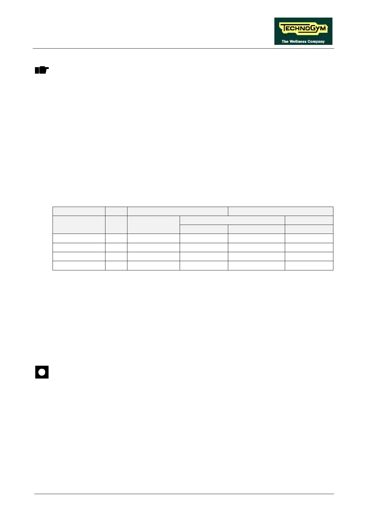
(1) Place the tester probes between the orange (positive) and black (negative) cables on the
alternator. Select the “Quick Start” function on the display and start exercising on the
machine. When the level of difficulty is varied, maintaining the speed indicated in Table
6.3-1, the excitation voltage should vary as shown in the same table:
Kg = 70 Excitation (Vdc) PWM signal (Vdc)
Alternator interface board CPU board Effort level SPM Alternator
4-5/CN2 6-3/CN1 6-3/CN1
1 17 2.8 2.8 3.3 3.3
3 30 1.8 1.8 3.7 3.7
6 50 0.76 0.76 4.0 4.0
9 80 0.27 0.27 4.9 4.9
Table 6.3-1
The voltages quoted above are nominal values and depend on the user weight.
(2) As for step (2) but with the tester between pins 4 and 5 of connector CN2 on the alternator
interface board.
(3) Disconnect all the cables from the 2 power resistor terminals. Place the tester probes on the 2
terminals and measure the value of the resistance. The correct value for the power resistor is
approximately 0.5 Ohm.
BE AWARE: Because all tester probes have a non zero internal resistance, which varies
depending on the model and may be in the same order of magnitude as the quantity
being measured, the following procedure is recommended:
1. Measure the internal resistance of the probes by short-circuiting them with each
other;
2. Measure the resistance of the power resistor;
3. The true resistance value is obtained by subtracting the short-circuit resistance of
the probes from the measured value.
(4) As for step (2) but with an oscilloscope between pins 6 and 3 of connector CN1 on the
alternator interface board.