ENGLISH
UPS EVO DSP PLUS Modular 47 User’s manual
On the front of Power Module, you can see the items described below (referring to the Figure 6.1 and 6.2).
The Power Module uses forced convection cooling by these fans. Cooling air enters
the module through ventilation grills and exhausted through grills located in the rear
of the module. Please do not block the ventilation area.
Unlock it before removing the Power Module.
Lock it when the Power Module is well installed. Then the Power Module can start to
work.
There are three DIP switches for Power Module Address setting, as explained in
chapter 6.1.
When AC input is not existing, use this button to start battery power for UPS.
The Power Module is in fault condition or the
Ready Switch is unlocked.
The Power Module IDs conflict.
The STS Module is not found.
The Power Module normally works as a Slave
Module.
The Power Module normally works as a Master
Module.
The CAN Bus communication doesn’t work.
6.1 Power Module ID
An exclusive identification number (Power Module ID) must be assigned to each Power Module.
The number ID is assigned via the DIP Switch #3 (on the front of Power Module) and via SW1 and SW2 Switches, as
explained in the Table 6-1 and 6-2. In the same cabinet; each Power Module ID MUST be exclusive.
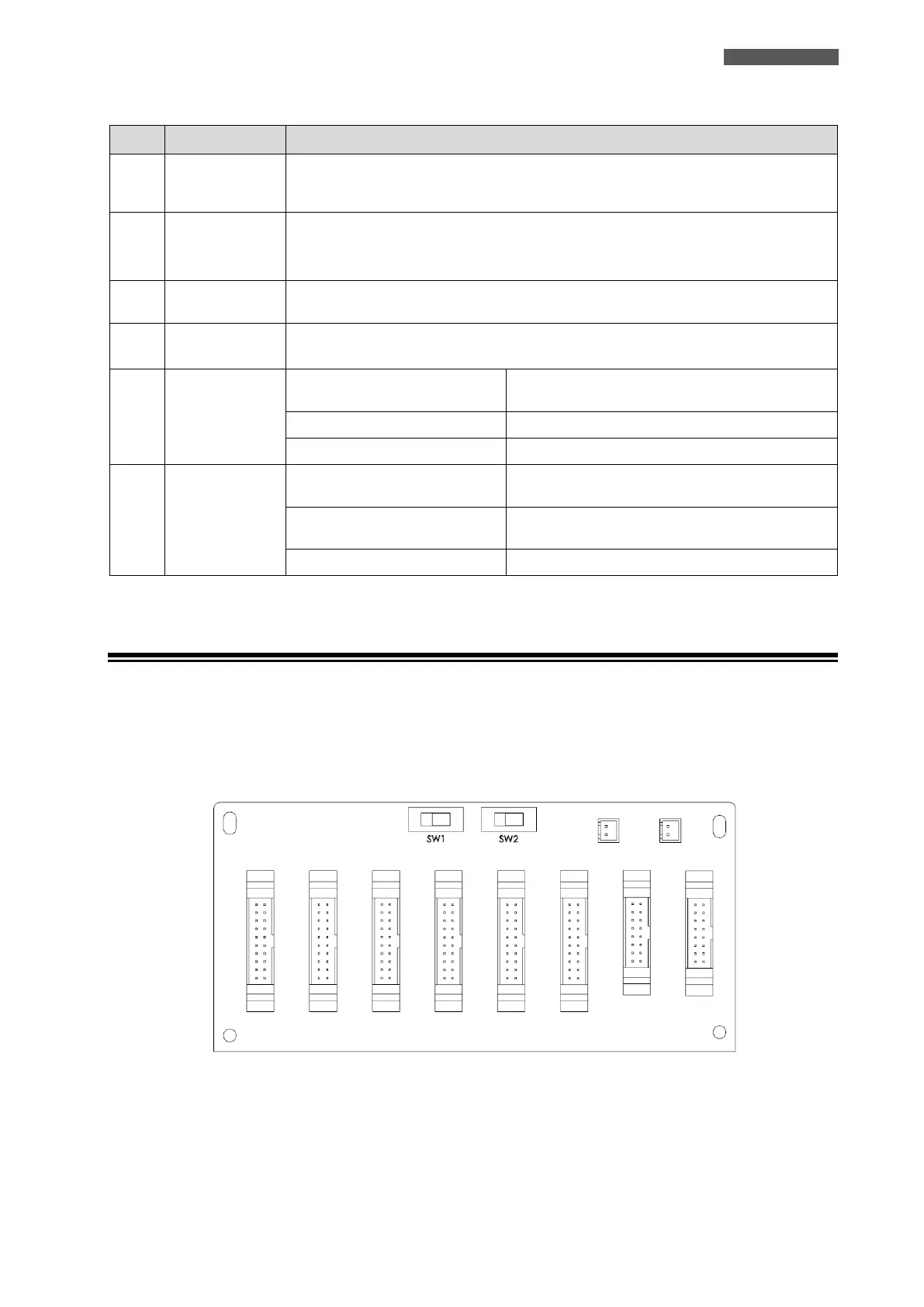
SW1 and SW2 Switches are mounted on the Parallel board, which is located at the back of UPS cabinet. Refer to
Figure 6.3.
Figure 6.3 – SW1 and SW2 Switches on Parallel Board