10 TEGAM WAY • GENEVA, OHIO 44041 • 440-466-6100 • FAX 440-466-6110 • sales@tegam.com
1-14
BROKEN LEAD DETECTION
A broken lead detection feature is enabled for ranges below 200 Ω when operating in either of the two
Delayed trigger modes. This feature is a function of the firmware and detects an open circuit by
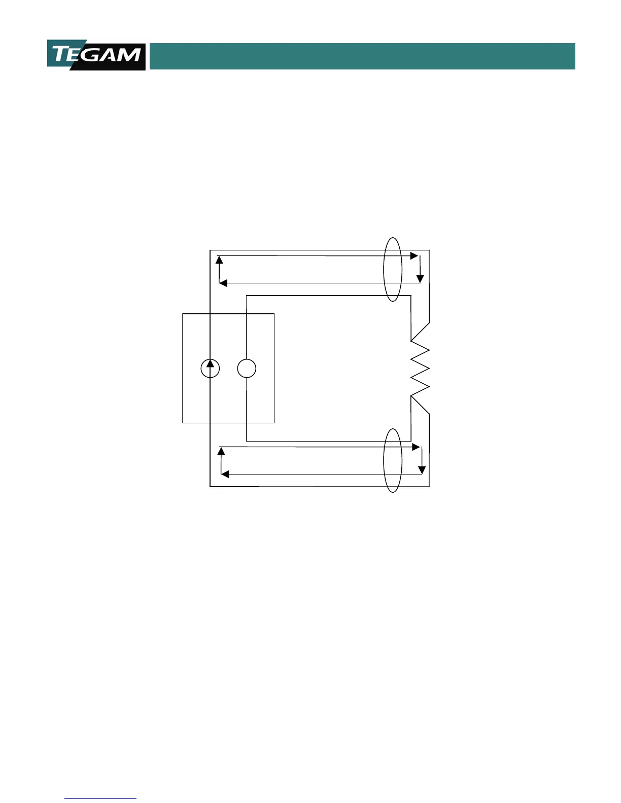
monitoring the test current characteristics. The illustration below represents the Kelvin leads and the
connection across a device under test. Note that there are three loops drawn with the arrows. Each of
these arrows shows the continuity test that is effectively performed by firmware during each read cycle.
If either the negative Kelvin loop, Positive Kelvin loop, or connection between the leads is broken, then
a broken lead state will be detected and the message “*****” is displayed on the LCD.
Fig 1.2: Continuity Test Paths for Broken Lead Detection