10 TEGAM WAY • GENEVA, OHIO 44041 • 440-466-6100 • FAX 440-466-6110 • sales@tegam.com
5-2
PROGRAMMING AND INTERFACING
REAR PANEL
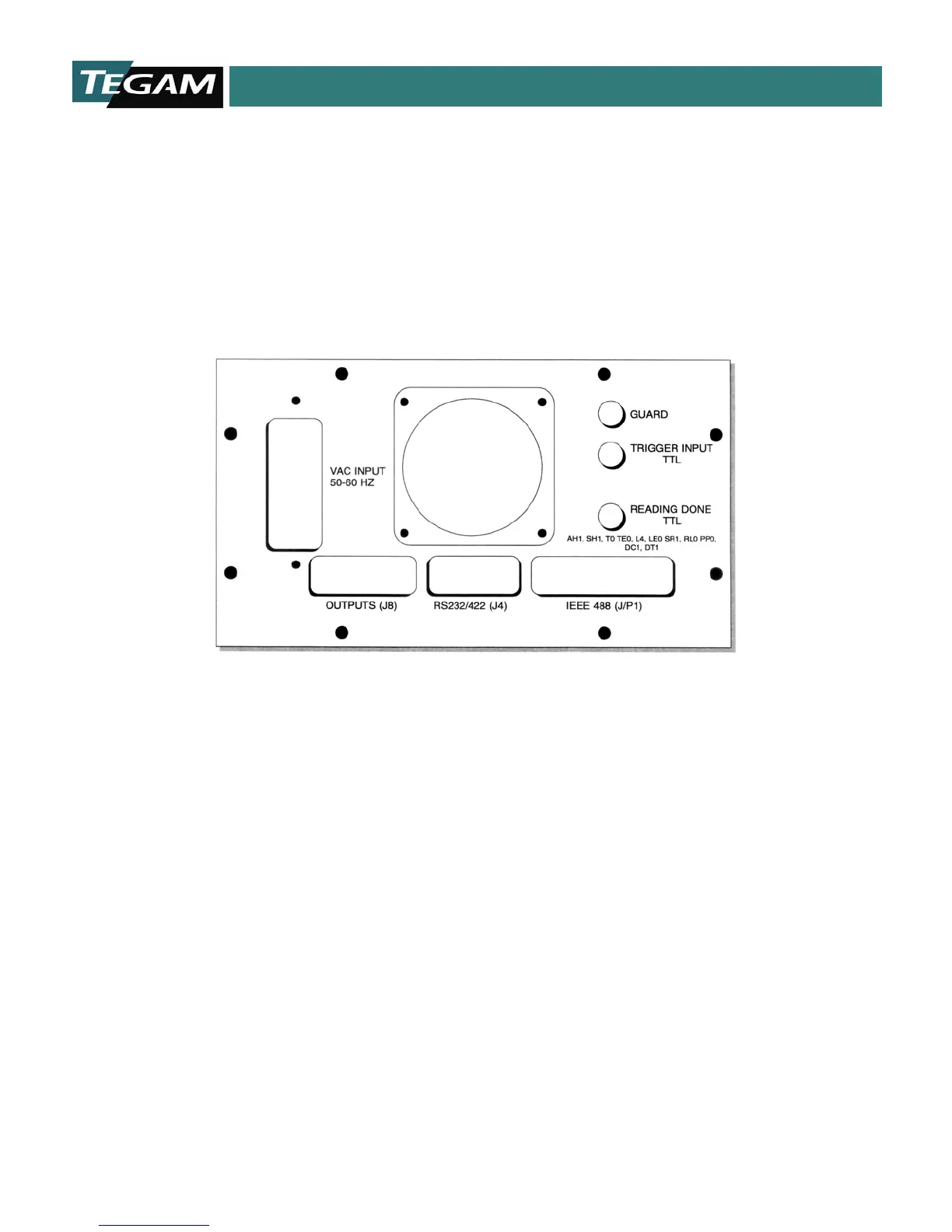
RS232, RS422 and GPIB communication ports are standard features of the Model 1750. These ports
are located in the rear panel of the unit. In addition to the RS232, RS422 and GPIB connectors, there
are two BNC connectors used for external control of the unit and a comparator output connector. These
input/output connectors have been added to simplify integration to PLCs and other control devices.
Below is an in depth description of these I/O connections and how they may be used with PLCs or other
test & measurement equipment.
Figure 5.2: Rear Panel
Trigger Input Connector
The first BNC connector is a Trigger Input, which requires a low TTL state to become active. Shorting
the center conductor of this BNC connector to ground, via relay contacts, is also an effective triggering
mechanism. The minimum period for the trigger pulse should be 10 ms for both TTL and relay contact-
type triggering. This minimum time allows the microprocessor to detect a low state while conducting
its routine monitoring of this input. The trigger input is periodically scanned after each read cycle.
Thus, the trigger input’s scan interval is dictated by the measurement mode and settings of the model
1750. Please refer to the section titled Reference Current Modes in Section 1, for illustrations of
various modes and how to determine their approximate measurement times.