10 TEGAM WAY • GENEVA, OHIO 44041 • 440-466-6100 • FAX 440-466-6110 • sales@tegam.com
1-12
TEST LEAD REQUIREMENTS
From the factory, the 1750 microohmmeter is equipped with the choice of either 17501 Kelvin Klips or
17502 Kelvin Spade Lugs. These are both 4-wire Kelvin input cables. Four-wire Kelvin-type cables must
be used with the 1750 in order to obtain an accurate resistance measurement.
The Kelvin measurement technique allows for a much more accurate reading over the two wire method.
This is because it eliminates lead resistance. This is done by designating two of the four conductors as
source leads. These source leads provide the precision test current that will be referenced in making
the resistance measurement. Since current is the same throughout a series circuit, the lead resistance
of the test leads will not have any effect on the reference current.
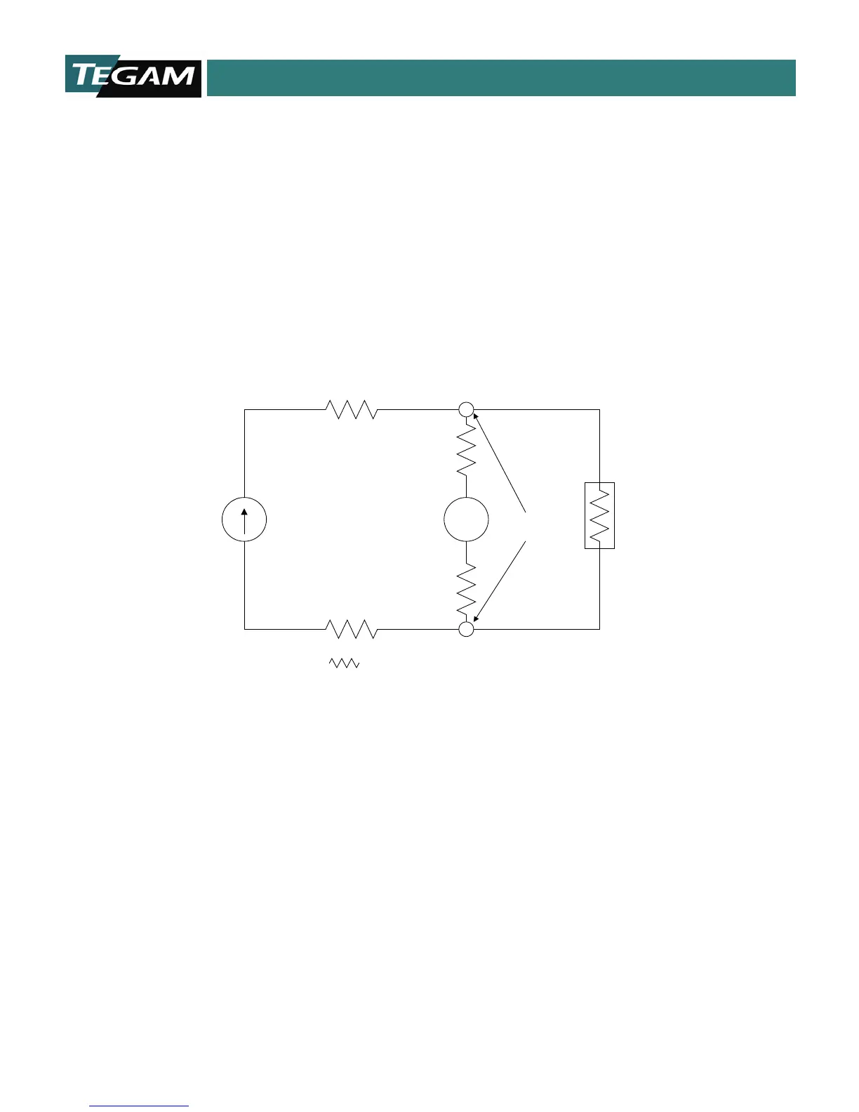
V
REFERENCE
CURRENT
SOURCE
VOLTAGE
SENSE
DUT
= SERIES LEAD RESISTANCE
CONTACT
POINTS
Figure 1.1: Electrical Representation of a typical Four-Wire Kelvin Measurement
The other two conductors are designated as voltage sense leads. These leads originate from high
impedance, volt measurement circuit. When these leads are terminated at the points of contact, an
exact resistance reading may be calculated by the 1750 microprocessor. The series lead resistance of
the voltage sense leads is negligible with respect to the high impedance of the voltage measurement
circuitry within the 1750 microohmmeter.
Four-wire Kelvin measurements are mainly used for low resistance measurements where lead
resistance errors must be eliminated.
Even though the four-wire Kelvin measurement minimizes the effect that lead resistance has on the
overall measurement, there is a maximum allowable lead resistance. If this value is exceeded, then the
resulting measurement will be erroneous. The test current source dictates this limitation and lead
resistance limits are based on the amount of reference current that is flowing. The table below
summarizes these limitations.