10 TEGAM WAY • GENEVA, OHIO 44041 • 440-466-6100 • FAX 440-466-6110 • sales@tegam.com
1-5
PERFORMANCE SPECIFICATIONS
The advertised specifications of the model 1750 are valid under the following conditions:
1. The instrument must be calibrated using the methods and intervals as described in the calibration
section of this user’s manual.
2. The instrument must be in an environment, which does not exceed the limitations as defined under
“Environmental” in the Miscellaneous Specifications in Section 1.
3. The unit is allowed to warm up for a period of at least 30 minutes before measurements are taken.
A warm-up period of 60 minutes is recommended after exposure to or storage in a high humidity,
(non-condensing), environment.
4. The Kelvin series lead resistances must not exceed the limitations as defined in Table1.1 or Table
1.7.
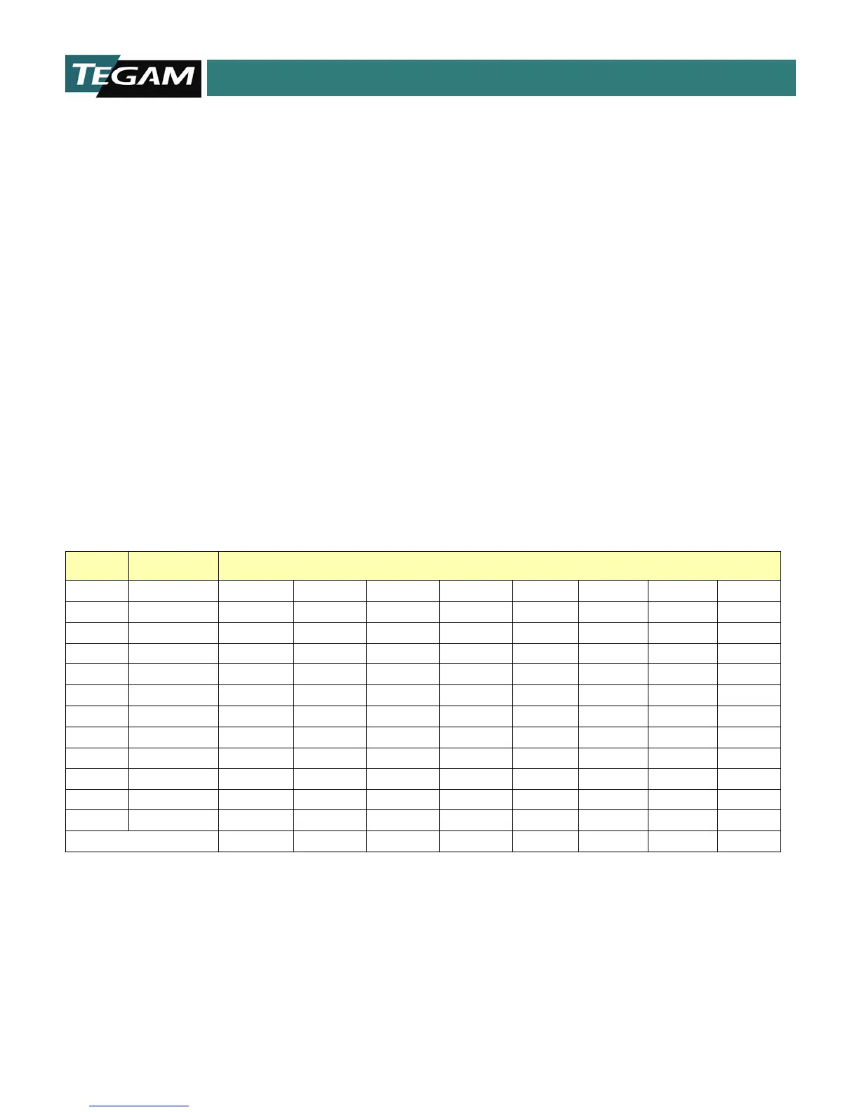
Table 1.1 below is a summary of the ranges and resistances available with the model 1750. It also
shows the full-scale voltage for each of the reference current ranges. The default ranges are printed in
BOLD. Absolute maximum lead resistances for each of the reference current ranges are included on
the bottom row. If these absolute maximum lead resistances are exceeded then significant error will be
introduced into the measurement.
RANGE RESOLUTION
REFERENCE CURRENT
1 A 100 mA 10 mA 1 mA 100 μA 10 μA 1 μA 100 nA
2 mΩ 100 nΩ 2 mV
20 mΩ 1 μΩ 20 mV 2 mV
200 mΩ 10 μΩ 200 mV 20 mV
2 Ω 100 μΩ 200 mV 20 mV
20 Ω 1 mΩ 200 mV 20 mV
200 Ω 10 mΩ 2 V 200 mV 20 mV
2 kΩ 100 mΩ 2 V 200 mV
20 kΩ 1 Ω 2 V 200 mV
200 kΩ 10 Ω 2 V
2 MΩ 100 Ω 2 V
20 MΩ 1 kΩ 2 V
Max. Lead Resistance 500 mΩ 5 Ω 50 Ω 100 Ω 100 Ω 100 Ω 100 Ω 100 Ω
Table 1.1: Full Scale Voltage as a Function of Reference Current