10 TEGAM WAY • GENEVA, OHIO 44041 • 440-466-6100 • FAX 440-466-6110 • sales@tegam.com
5-3
PROGRAMMING AND INTERFACING
Trigger Out Connector
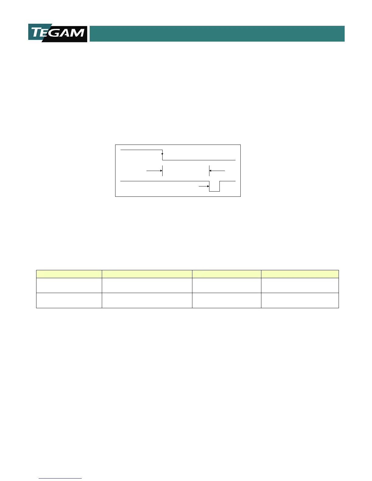
The second BNC connector provides a TTL level, Done Pulse. The Reading Done outputs’ normal state
is +5 V. Once the 1750 completes a measurement cycle, the state of the output goes to a low state
for approximately 4.5 ms, and then returns to +5 V. Its state is updated after each read cycle. Below
is an illustration that displays the functions of the TTL input and output. There is also a table of
electrical specifications for these outputs.
Trigger Input and Reading Done TTL Outputs.
(BNC Connectors)
BNC connector, active low
MIN:>3.5 VDC
MAX: <5.3 VDC
Trigger Output
(Reading Done)
BNC connector, >4.25 ms,
active low pulse
Table 5.1: Trigger I/O Electrical Requirements (V
DD
= 5.0 VDC)
TIME TO FIRST
READING
TRIGGER IN
READING DONE
>4.25 mS