10 TEGAM WAY • GENEVA, OHIO 44041 • 440-466-6100 • FAX 440-466-6110 • sales@tegam.com
5-1
PROGRAMMING AND INTERFACING
SECTION 5
PROGRAMMING AND INTERFACING
INTERFACING TO THE 1750
This section provides detailed information about the model 1750 electrical interfaces and their
functionality. It will provide all of the necessary information required to integrate the 1750 easily into
a working test stand. Only one communication interface may be used at a time. The 1750 is shipped
from the factory with a default RS232 communications setting. To change the communications setting,
refer to the menu navigation chart on page 4-13.
The command sets for the RS232, RS422 and GPIB communication are virtually identical. However,
because of the minor differences, this section separates RS232 and RS422 from GPIB to simplify the
description of operating principles.
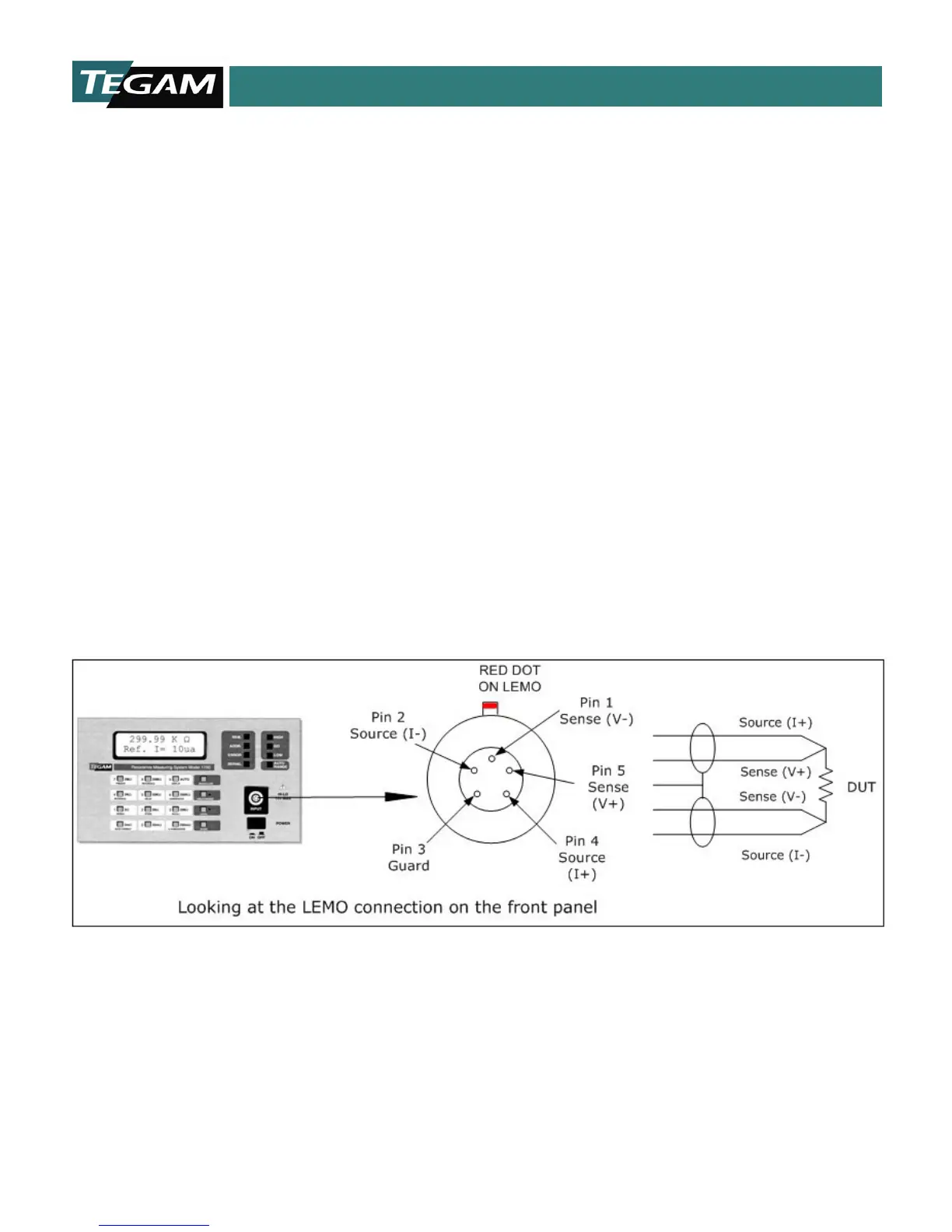
FRONT PANEL
The Model 1750 uses a four-wire, Kelvin type connection to make resistance measurements. This Kelvin
connection is located on the instruments front panel. There are five connections used on this connector.
Two source leads, which send the bipolar test current through the DUT, two voltage sense leads that
detect the voltage drop across the DUT, and a shield connection for protection against external electrical
interference. The orientation of the front panel LEMO connector is illustrated below:
Figure 5.1: Lemo Connector
NOTE: When constructing custom test leads for a test fixture etc., the maximum allowable lead resistance
limits must not be exceeded. Refer to Table 1.7 in Section 1 for a summary of maximum lead resistance
limits for each of the reference current ranges. Use shielded cable, grounded on one end only, to minimize
external interference. Also, take special care in assuring proper contact to the DUT when taking
measurements.