10 TEGAM WAY • GENEVA, OHIO 44041 • 440-466-6100 • FAX 440-466-6110 • sales@tegam.com
4-5
Resistance Mode
The 1750 factory default setting is the Resistance Mode. Below is a representation of the Resistance
Mode display and a brief description of each of the display fields.
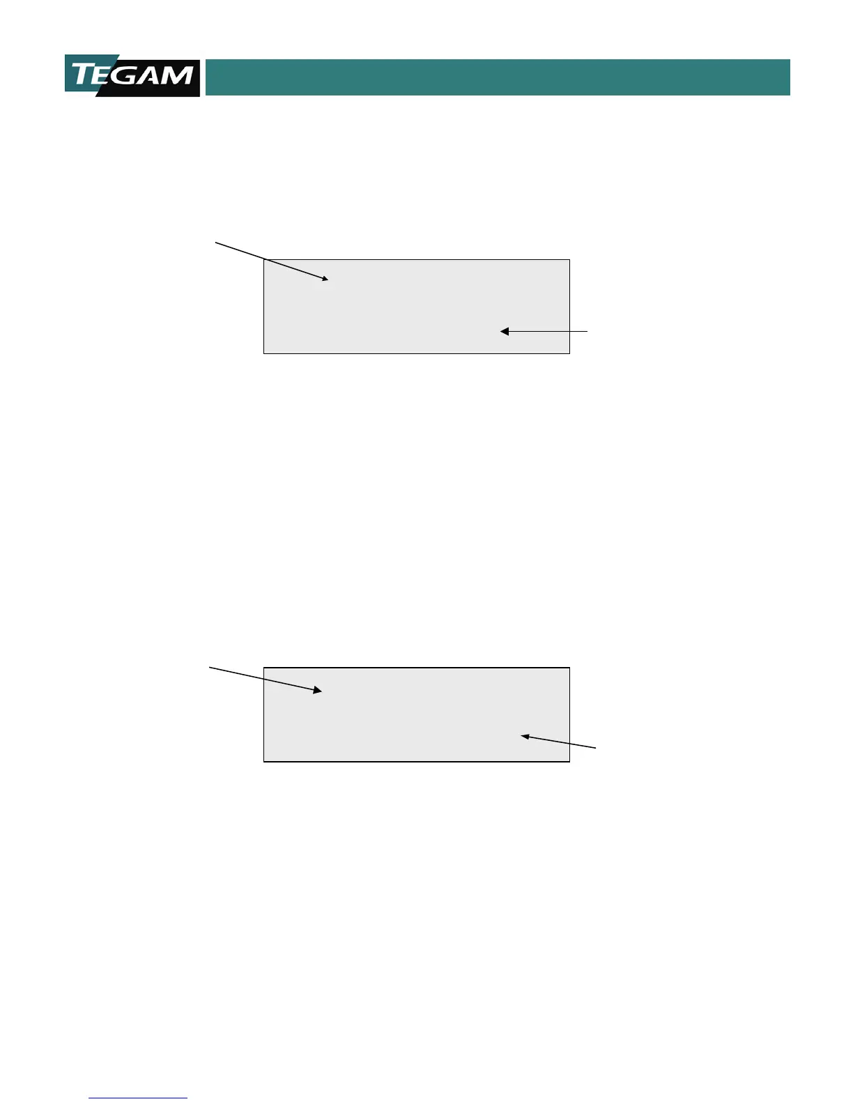
Figure 4.4: Resistance Mode
Resistance Reading
This field is reserved for display of the resistance measurement value or status. There are 4 ½ digits
of resolution for all ranges of resistance and test currents. The reading is updated once every
measurement cycle in the Continuous Trigger Mode. The actual cycle time of the continuous mode is
dependent on whether the unit is in Delayed Continuous or Fast Continuous Mode. Refer to Section
1, for detailed timing diagrams and a formula for calculating total measurement times. When the
1750 is operating in the Delayed One-Shot or Fast One-Shot Mode, the resistance reading is updated
one measurement cycle after a manual trigger is received. These actual measurement times may
also be determined by referencing Section 1.
Figure 4.5: Over Range or Open Lead Condition
Open Lead Detection
The 1750 includes an Open Lead Detection feature, which is active in the 20 Ω, 2 Ω, 200 mΩ, 20
mΩ, and 2 mΩ ranges. It verifies the continuity of the test leads and contacts when the 1750 is
operating in either of the two delayed trigger modes, (Delayed Continuous or Delayed Trigger). The
Kelvin measurement technique requires that four wires be used in making a measurement. If any of
these leads or a combination of these leads is open, then the instrument shall display “
*****”,
which is the equivalent of an over range condition. For RS232 and GPIB operation, the unit will send
a “2.9999” ASCII string, which is also the equivalent of an over range condition.
Range or Open Lead
Condition
Status
Ω