10 TEGAM WAY • GENEVA, OHIO 44041 • 440-466-6100 • FAX 440-466-6110 • sales@tegam.com
4-2
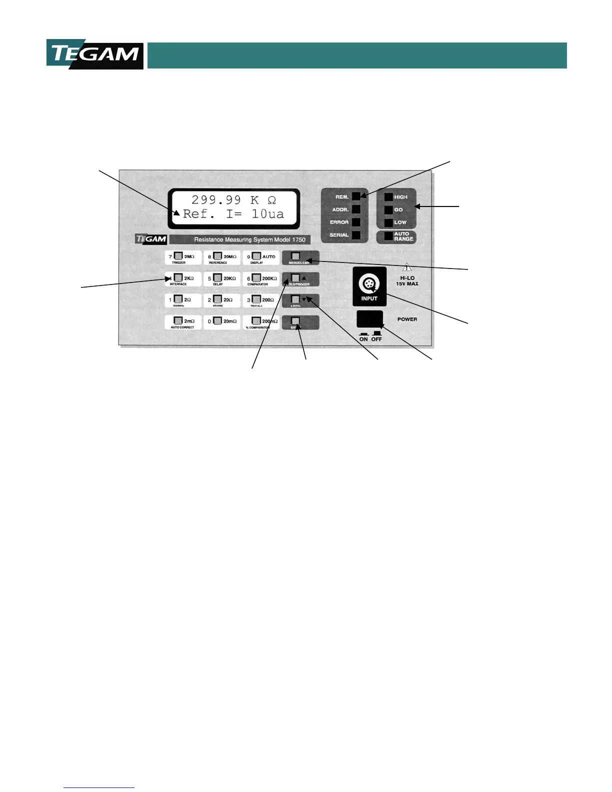
FRONT PANEL DESCRIPTION
Figure 4.1: Front Panel Layout
Liquid Crystal Display - Indicates the resistance
measurement, resistance range, comparator settings,
communication type, and other operating conditions. See
“Display Modes” in this Section for details of display
operation.
Numeric Keypad – Numeric keypad includes 0-9 keys for
entering values for menu items, delay times or
comparator/bin limits.
Hold/Manual Trigger Key – This key allows the user to
either HOLD the measurement when operating in Continuous
Trigger Modes or to TRIGGER a reading in the One-Shot
Modes. It also functions as the scroll up, [▲], key when the
unit is in parameter mode.
Parameter Menu Enter Key – The [ENTER] key is used for
inputting parameter settings for any of the menus or for
storing numerical data.
Local Mode Key –Pressing this key permits the user to
access front panel controls while the unit is operating in
remote mode. The unit returns to remote mode from local
mode after receiving a command from the GPIB or RS232
interface.
The local key also functions as the scroll down, [▼], key
when the menu mode is selected.
If the internal calibration jumper is enabled, pressing this
button will switch the 1750 into debug mode. This feature is
Power Switch – Powers the 1750.
Kelvin Input LEMO Connector – Heavy Duty Input
Connector for Kelvin Klips™, Spade Lug Adapter, Kelvin
Probes or Test Fixture using 5 conductor, male LEMO.
Menu Scroll Keys – The scroll keys will allow the
navigation of the Menu Screens by pressing either the [▲
or [▼] keys.
Menu Selection Key – Pressing this key will toggle the
function of the numeric keypad for accessing and defining
instrument parameters.
Comparator Output LEDs - LEDs indicate status of
comparator after measurement cycle. LED status
corresponds to comparator relay and TTL outputs on rear
panel connector, J8.
Communication Status LEDs – Indicate the error and
status of communications RS232, RS422 & GPIB.
High Speed Programmable Micro-Ohmmeter Model 1750
High Speed Programmable Micro-Ohmmeter Model 1750
Display
Key
LEMO Connector
Output LEDs
Key
Menu Enter
Key
Trigger Key
Keypad
Status LEDs