10 TEGAM WAY • GENEVA, OHIO 44041 • 440-466-6100 • FAX 440-466-6110 • sales@tegam.com
4-3
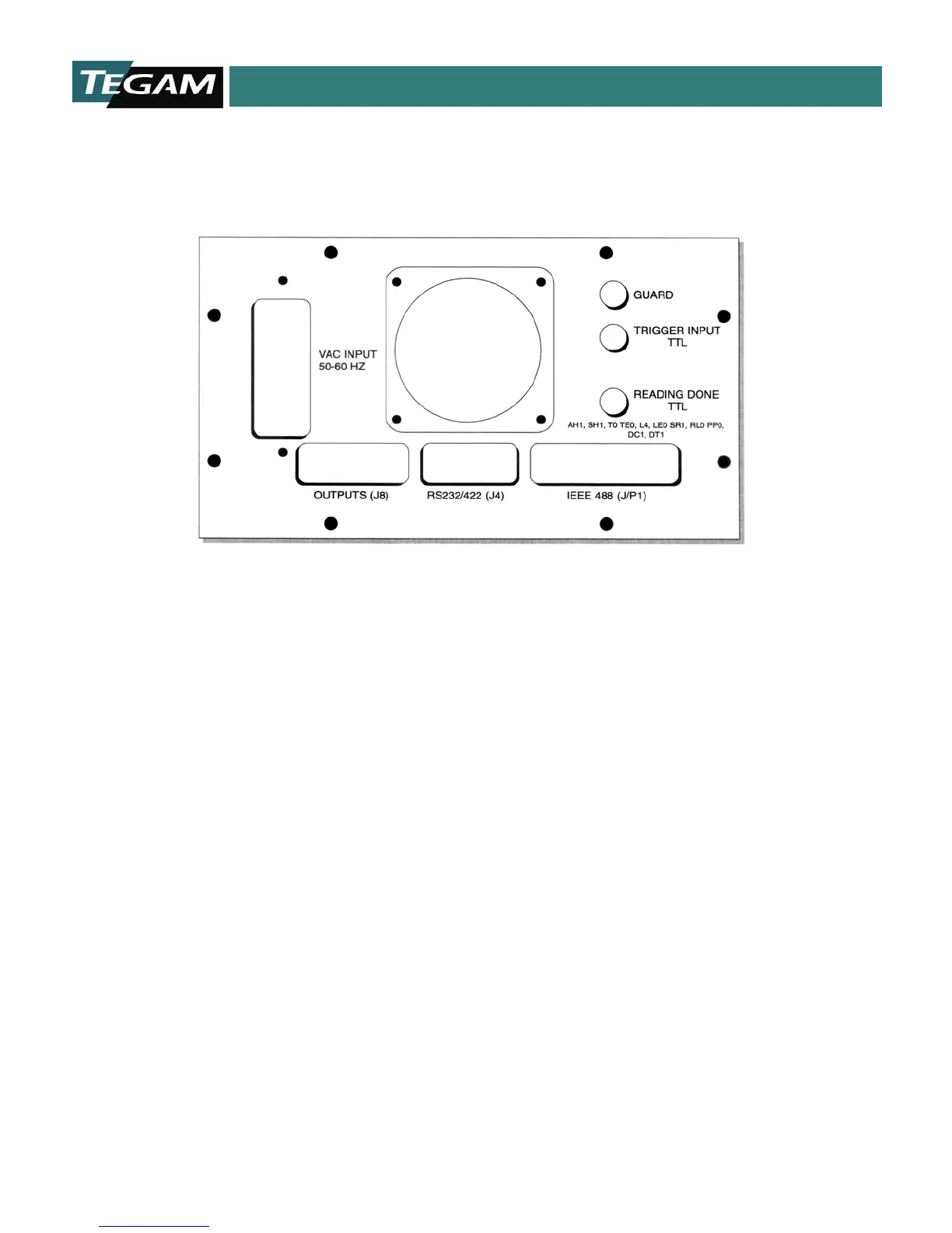
REAR PANEL DESCRIPTION
Figure 4.2: Rear Panel Layout
BNC Reading Done TTL Output – Open Collector TTL
Output. Output is at +5 V until a complete reading cycle
has occurred. A negative going pulse occurs for about 4.25
ms then the output state returns to +5 V.
BNC Trigger TTL Input – A TTL low into this input will
activate a trigger command. A trigger will also occur if the
input is shorted to ground via relay or other contact for a
minimum of 10 ms.
J8 – Relay and TTL I/O Connector – See Section 5,
Interfacing to the PC for pin out details.
VAC Input – 120/240 V @ 50/60 Hz, power input. Line
fuse is accessible through this input.
GPIB (IEE-488.2) Port - See Section 5, Interfacing to
the PC for pin out details.
RS232 Port - See Section 5, Interfacing to the PC for
pin out details.
RS422 Port - See Section 5, Interfacing to the PC for
pin out details.
Guard Terminal – Banana connection to the 1750 test
signal current source (common), typically used for
reducing noise in high resistance, (>20 kΩ)
measurements.
Cooling Fan –
20 CFM maximum airflow. Operation is 5
V @ 240 mA.