10 TEGAM WAY • GENEVA, OHIO 44041 • 440-466-6100 • FAX 440-466-6110 • sales@tegam.com
4-7
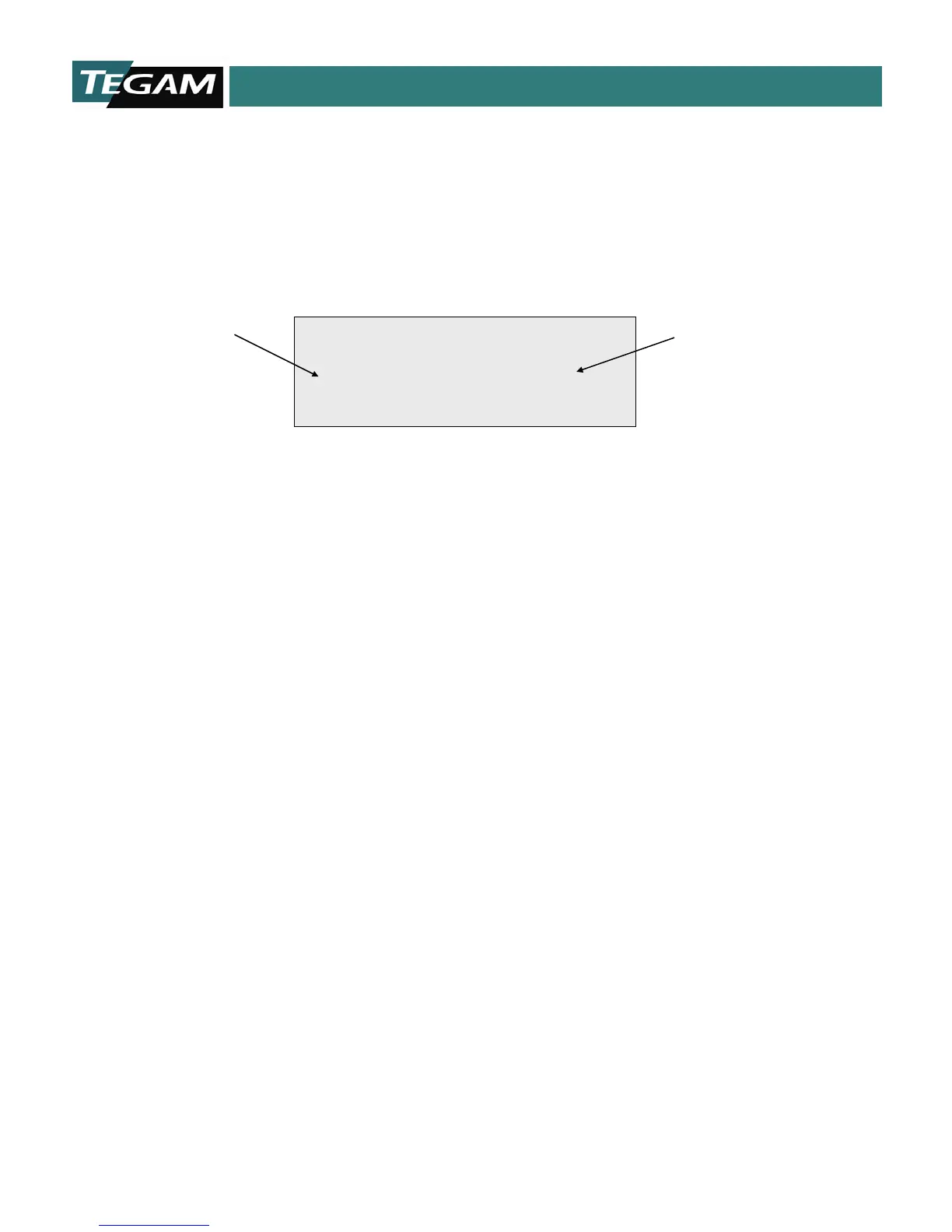
Absolute Comparator Mode
In the Absolute Comparator Display Mode, the screen will look like the Resistance Display Mode
except that the reference current indication is replaced by two additional fields of data. On the left
side is the high limit, absolute value. On the right side is the absolute low, comparator limit.
Figure 4.6: Absolute Comparator Mode
The above display indicates that the meter is in the 2 MΩ range. The high limit is set to 20,000
counts of full scale, which is 2 MΩ. The low limit is set to 10,000 counts, which is the equivalent to
1 MΩ in this scale. Note that the comparator limits are programmed in counts rather than Ohmic
units. This means that the comparator resistance values are determined by both the active range
and the user defined limit values.
High & Low Absolute Comparator Limit
Fields indicate the user-defined upper and lower limits for the absolute comparator function. If the
measured resistance reading exceeds the high limit, and the comparator mode is active, then the
corresponding “HI” state will transfer to the Comparator State LED. If the current reading falls on or
between the HI and LO comparator limits, then the “GO” LED becomes illuminated. And finally, if the
reading falls below the low limit then the “LO” comparator output is activated. The TTL and Relay
comparator outputs in the rear panel follow the front panel comparator LED states. All comparator
outputs are disabled when the 1750 is operating in the resistance mode.
Ω
Comparator Limit
Comparator Limit