10 TEGAM WAY • GENEVA, OHIO 44041 • 440-466-6100 • FAX 440-466-6110 • sales@tegam.com
4-8
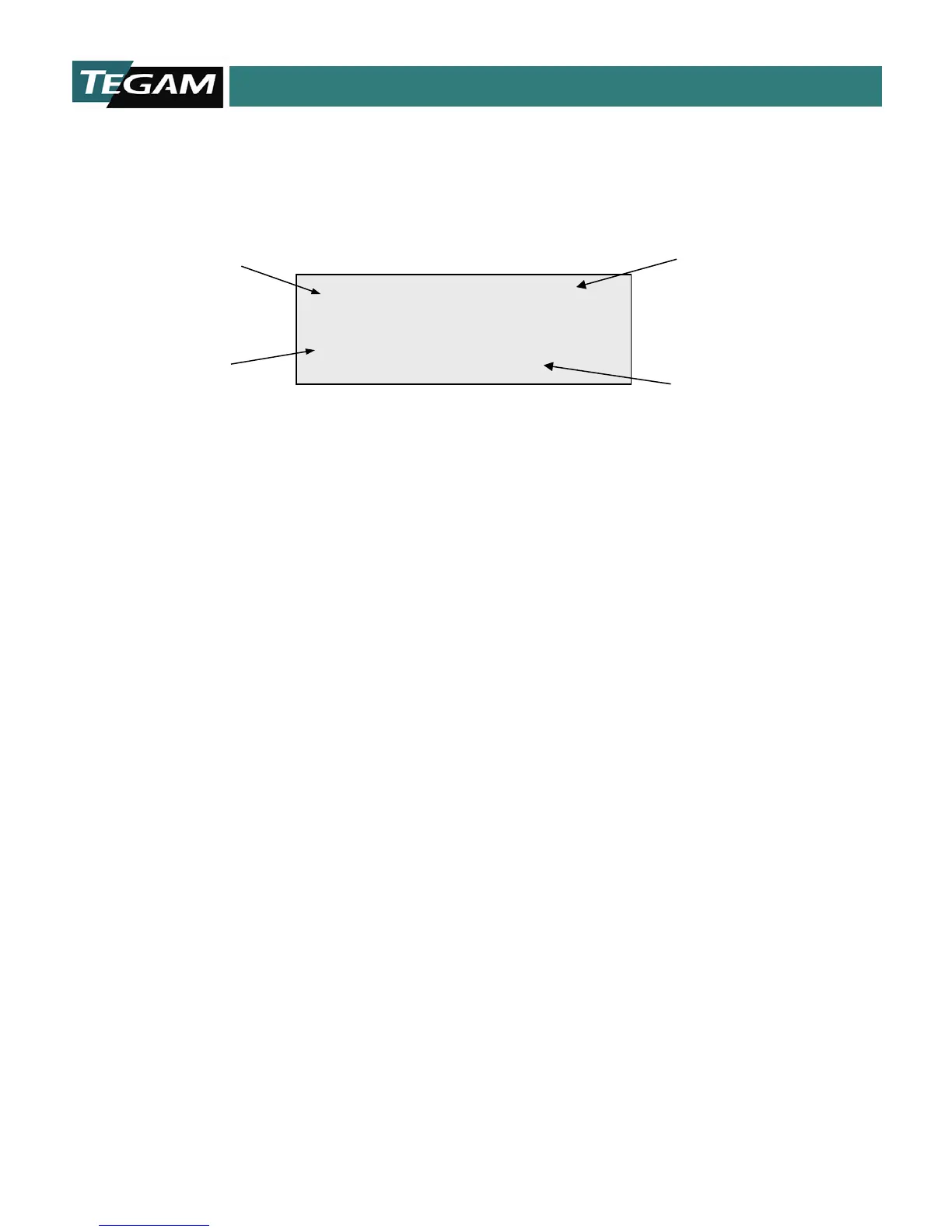
% Comparator Mode
Figure 4.7: % Comparator Mode
High% & Low% Absolute Comparator Limit
The % Comparator Display Mode is similar to the Absolute Comparator Mode in that the user defines
the upper and lower limits of the resistance measurement. However, these limits are defined in terms
of a high and low percentage of a nominal value instead of an absolute value. The comparator state
is indicated by the front panel LEDs and is transferred to the TTL and Relay outputs of the rear panel.
Nominal Resistance Value
In the upper right-hand corner of the display, the user-defined nominal value is displayed. High and
low % comparator values are calculated by the 1750 from the user-defined nominal value. In the
illustration above, the nominal value is set for 10 MΩ. The high limit is set for all readings above 11.0
MΩ, (10 M+1 M) and the low limit is set for all readings below 9 MΩ (10 M-1 M).
Reading
Comparator Limit