Calibration
6–20
1502C MTDR Service Manual
2. Use the
n
o
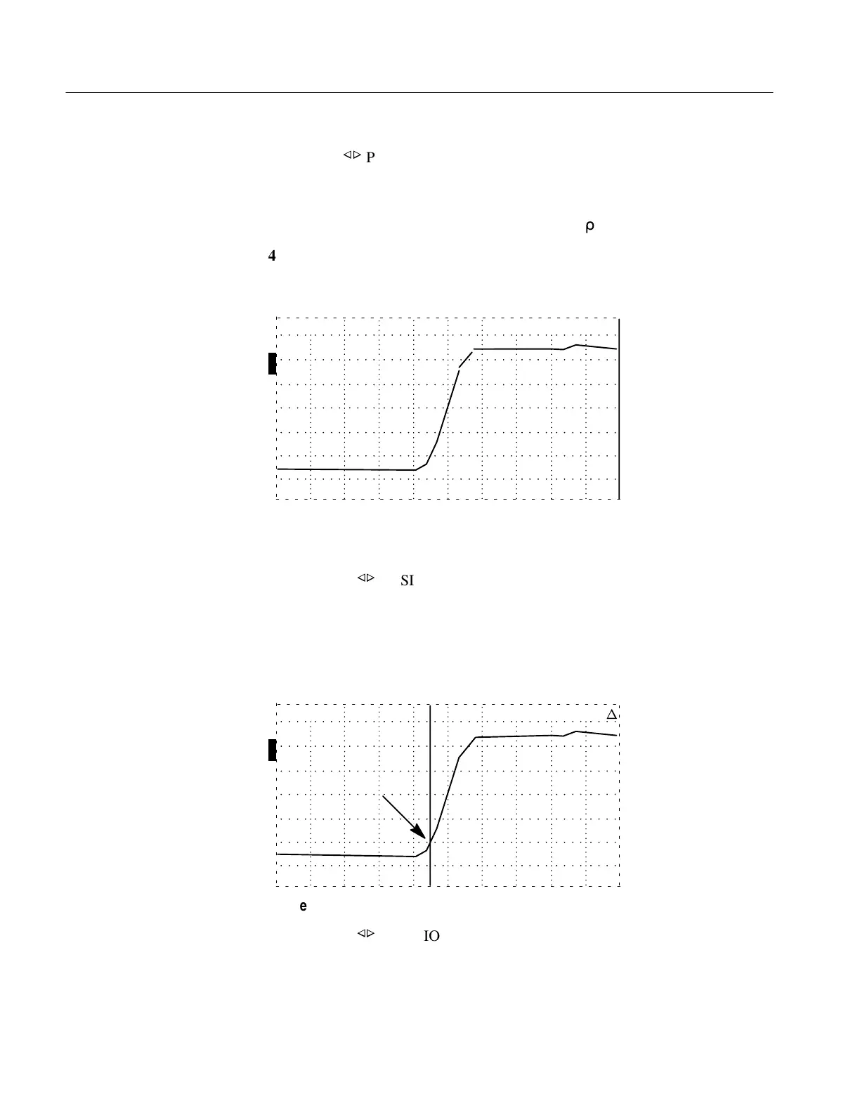
POSITION control to move the incident pulse to the center of the
display (as shown in Figure 6–32).
3. Turn the VERT SCALE control clockwise until the leading edge of the incident
pulse is five major divisions high (about 200 m
r
).
4. Position the waveform so that it is centered horizontally and vertically on the
middle graticule lines (2.5 divisions below the center horizontal graticule line
and 2.5 divisions above).
O
F
F
O
N
ac
O
F
F
O
F
F
–0.316 ft
Figure 6–33: Incident Pulse Centered, Vertical Increased
5. Turn the NOISE FILTER control to HORZ SET REF.
6. Using the
n
o
POSITION control, set the cursor to the point where the lower
portion of the pulse’s rising edge first crosses a major horizontal graticule line
(should be about half a division from the bottom of the pulse).
7. Press STORE.
8. Turn the NOISE FILTER to 1 avg.
O
F
F
O
N
ac
O
F
F
O
F
F
0.000 ft
n
Figure 6–34: Cursor on Rising Edge at First Horizontal Graticule
9. Using the
n
o
POSITION control, set the cursor to the point where the upper
portion of the pulse’s rising edge crosses a major horizontal graticule line
(should be about half a division from the top of the pulse).
Artisan Technology Group - Quality Instrumentation ... Guaranteed | (888) 88-SOURCE | www.artisantg.com