Calibration
6–10
1502C MTDR Service Manual
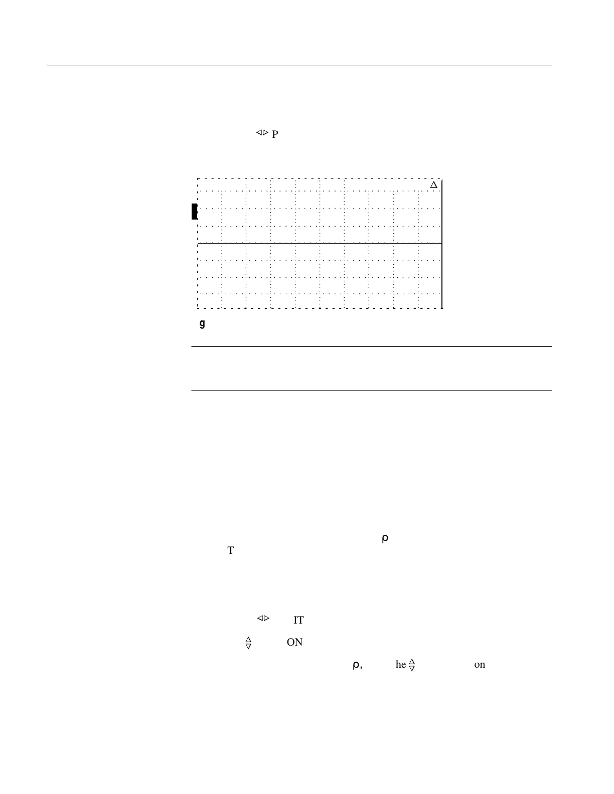
13. Set the DIST/DIV control to 200 ft/div.
14. Rotate the
n
o
POSITION control clockwise until the display distance window
shows a distance greater than 2,000.000 ft. The waveform should remain flat
from zero to this distance.
O
F
F
O
F
F
O
F
F
O
N
ac 2043.000 ft
n
Figure 6–15: Flatline Display to >2,000 ft
NOTE. If the Timebase does not appear to be working properly, refer to the Circuit
Descriptions chapter and the Troubleshooting section of the Maintenance chapter
of this manual.
Zero Offset Check
If the instrument fails this check, you might still make some tests, but the offset
might change when cable conditions change.
1. Set the front-panel controls:
CABLE (see * below)
NOISE FILTER 1 avg
VERT SCALE 500 m
r
DIST/DIV .2 ft/div
V
P
.99
POWER ON
* Nothing should be connected to the front panel CABLE connector.
2. Adjust the
n
o
POSITION control so the distance window reads –2.000 ft.
3. Use the
n
o
POSITION control to center the baseline before the incident pulse.
4. Increase VERT SCALE to 10 m
r
,
using the
n
o
POSITION control to keep the
baseline centered on the display.
Artisan Technology Group - Quality Instrumentation ... Guaranteed | (888) 88-SOURCE | www.artisantg.com