Calibration
1502C MTDR Service Manual
6–7
12. Rotate the
n
o
POSITION control slowly in either direction. The lower value in
each column should be between 0 and 10 while the higher number is between
245 and 255.
13. Rotate the VERT SCALE control slowly in either direction. The lower value
in each column should be between 0 and 10 while the higher number is between
245 and 255.
There is a numerical reading from the thermistor located on the LCD. If it is not
operating properly, the LCD heater might not come on in cold environments. This
could result in slow or unreadable displays.
1. The displayed temperature reading should be between 50 and 90, depending on
the ambient temperature. If the thermistor is defective, the reading will be near
0 or 255.
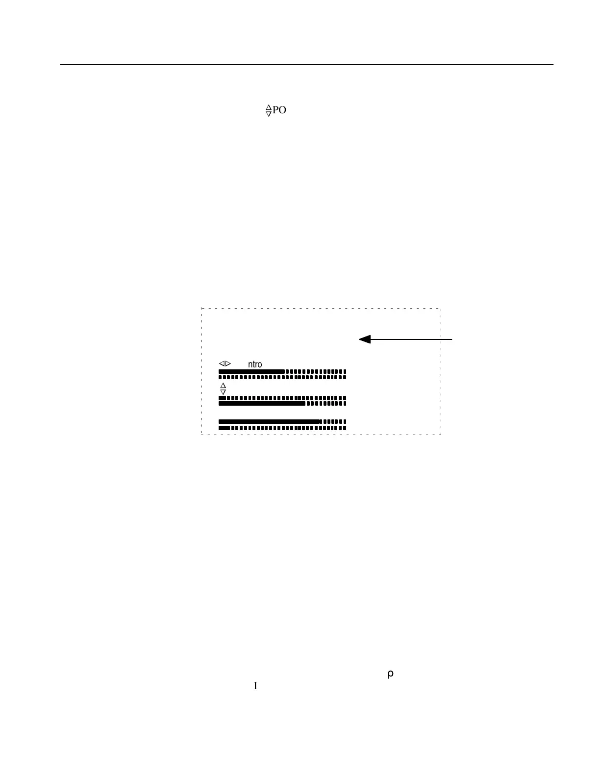
Front Panel Diagnostic, test all switches.
Hold down MENU button to Exit.
Switch: 1 temp: 78
Vp: 0.30
n
o
n
o
Control
Control
Vertical Scale
142
11
190
0
181
24
Temperature
Reading
Figure 6–9: Front Panel Diagnostic Display
2. Press MENU repeatedly until the instrument returns to normal operation.
If any of the controls or functions are defective or indicate erratic response, the
function affected by that control could be in error. The defective control should be
replaced. See the Maintenance chapter of this manual.
Horizontal Scale (Timebase) Check
If the instrument fails this check, it must be repaired before any distance
measurements are made with it.
1. Set the front-panel controls:
CABLE No connection (see text)
NOISE FILTER 1 avg
VERT SCALE 500 m
r
DIST/DIV .1 ft/div
V
P
.66
Thermistor
Conclusion
Artisan Technology Group - Quality Instrumentation ... Guaranteed | (888) 88-SOURCE | www.artisantg.com