Calibration
6–38
1502C MTDR Service Manual
If the Contrast Adjust is set properly, you will be able to see the cursor clearly when
it is moved rapidly across the display. If any residual images are made by the cursor
movement, they should fade out quickly.
NOTE. If you are unable to adjust the contrast, or if pixels are not functioning, see
the Troubleshooting section in the Maintenance chapter of this manual.
Zero Offset Adjust
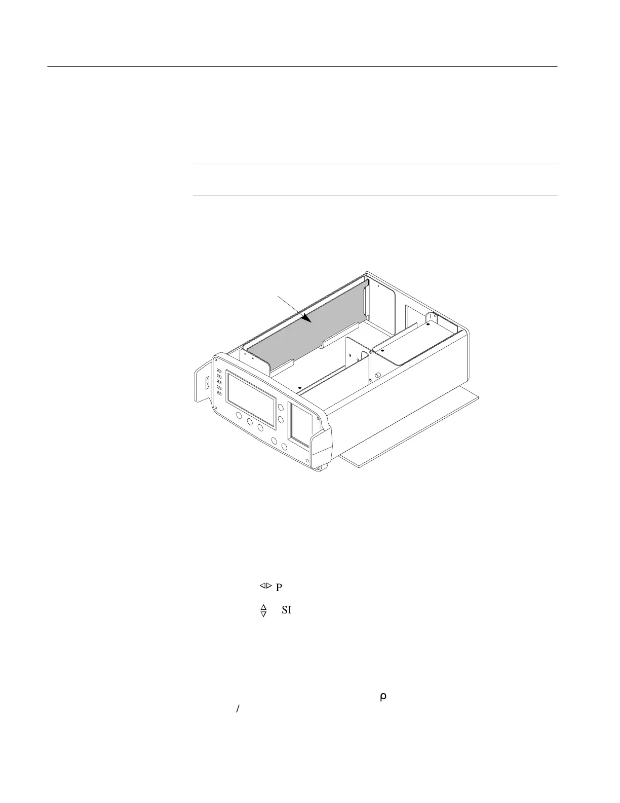
The following adjustment is located on the Driver/Sampler Board.
Driver/Sampler Board
Figure 6–63: Driver/Sampler Board Location
1. Turn off the POWER to the instrument.
2. Remove the EMI shield covering the Driver/Sampler Board (see Maintenance
chapter).
3. Turn the POWER on.
4. Adjust the
n
o
POSITION control until the distance window reads –2.000 ft.
5. Adjust the
n
o
POSITION control to center the baseline on the center horizontal
graticule line (see Figure 6–64, next page).
6. Set the front-panel controls:
CABLE no connection
NOISE FILTER 1 avg
VERT SCALE 10 m
r
DIST/DIV 0.2 ft/div
V
P
.99
Artisan Technology Group - Quality Instrumentation ... Guaranteed | (888) 88-SOURCE | www.artisantg.com