Calibration
1502C MTDR Service Manual
6–39
O
F
F
O
F
F
O
F
F
O
N
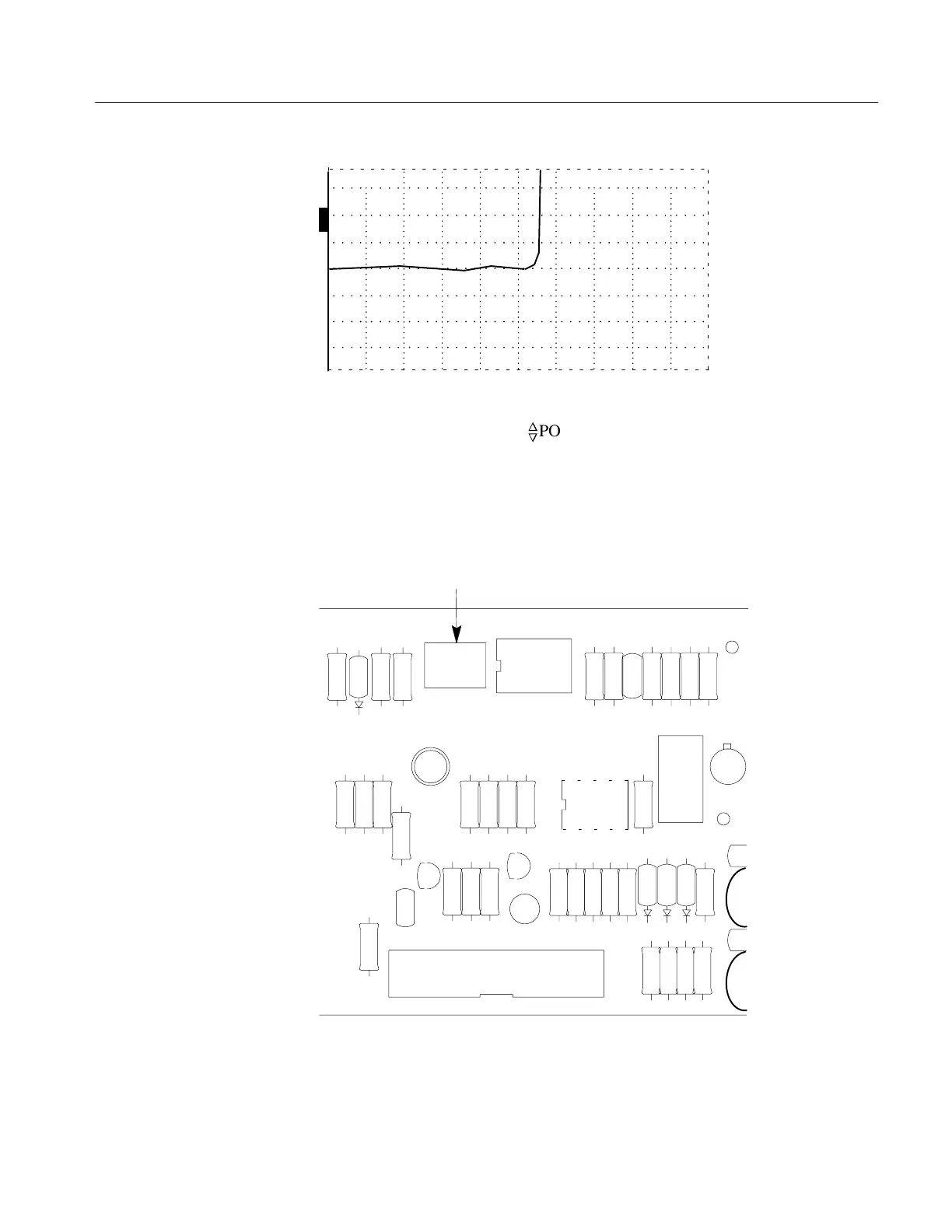
ac –2.000 ft
Figure 6–64: Incident Pulse at –2.000 ft
7. If necessary, readjust the
n
o
POSITION control to center the baseline on the
center horizontal graticule line.
8. Attach the 3-foot precision cable to the front-panel CABLE connector. This will
probably cause the waveform to move slightly on the display.
9. Adjust R1042 (Zero Offset) to move the waveform to the same position as when
no connector was attached to the front panel.
R1042
U1050
C1041
U2050
Q1060
TP
C2051
J3040
C3
C3
TP106
C1040
CR1040
R1040
R1041
R1050
R1051
C1050
R1052
R1053
C1060
C1061
R2040
C2040
R2041
R2045
R2042
R2043
C2041
C2050
R2050
C2053
R3040
C2042
Q2040
R2046
R2047
R2048
Q2050
R2049
R2051
R2052
R2053
R2054
CR2050
CR2051
CR2052
C2052
R3050
R3051
C3060
C3061
123
Figure 6–65: R1042 on Driver/Sampler Board
10. Remove the 3-foot precision cable.
11. Verify that the waveform moves less than 0.5 division.
Artisan Technology Group - Quality Instrumentation ... Guaranteed | (888) 88-SOURCE | www.artisantg.com