Calibration
1502C MTDR Service Manual
6–35
3. Using a precision Ohmmeter, measure the resistance from the 0.6 VDC supply
(TP1030) to the center conductor of the front-panel CABLE connector.
4. Subtract the resistance of the Ohmmeter test probes. The result should be
between 49.5
W
and 50.5
W
.
LCD Check and Adjustment
1. Turn POWER on.
2. Push MENU.
3. Using the
n
o
POSITION control, scroll to Diagnostics Menu.
4. Push MENU.
5. Scroll to LCD Diagnostics Menu.
6. Push MENU.
7. Scroll to LCD Alignment Diagnostic.
8. Push MENU.
R1018
Figure 6–57: R1018 on Front Panel Board
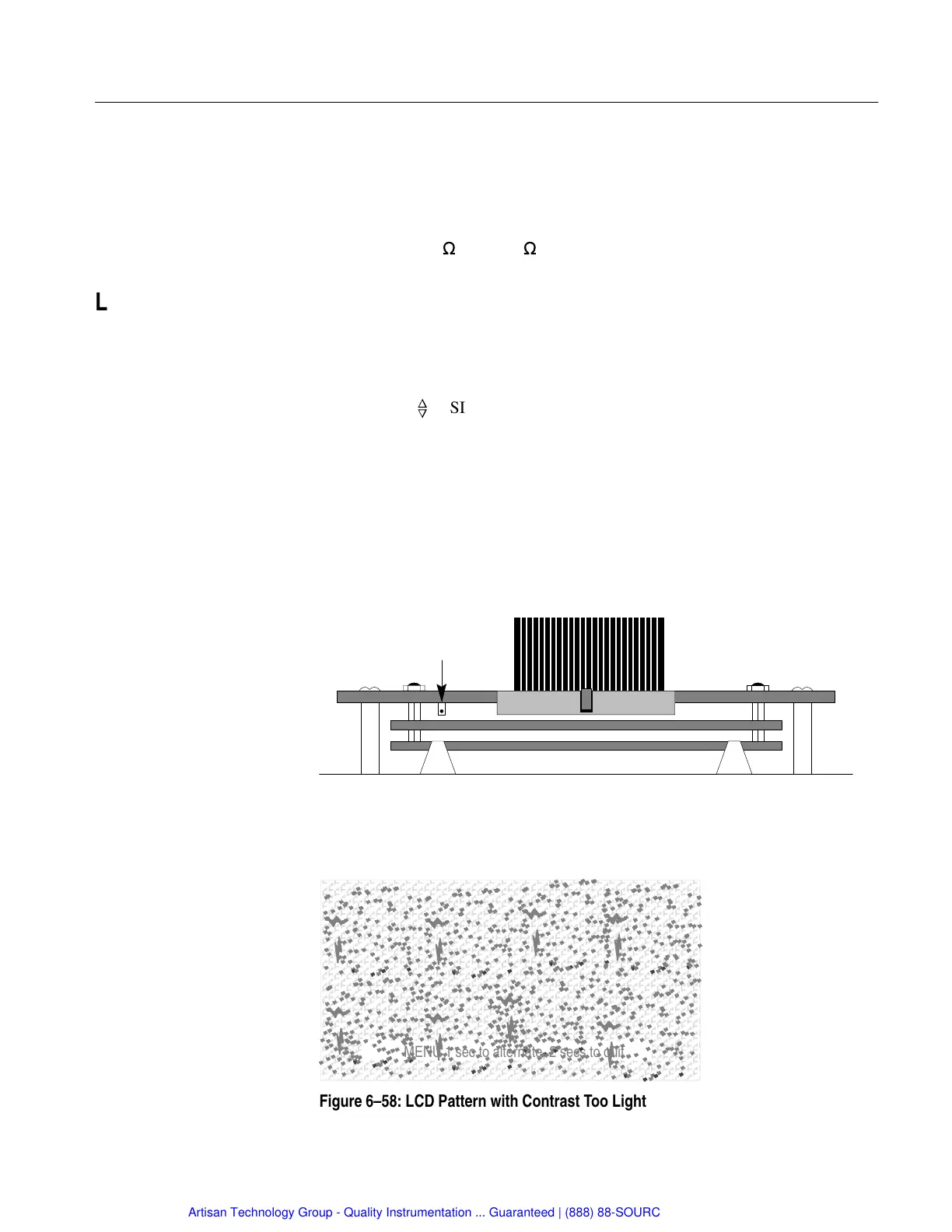
9. Observe the LCD as you adjust R1018 (Contrast Adjust) counterclockwise until
the entire pattern starts to dim.
ÄÄÄÄÄÄÄÄÄÄÄÄÄÄÄÄÄ
ÄÄÄÄÄÄÄÄÄÄÄÄÄÄÄÄÄ
ÄÄÄÄÄÄÄÄÄÄÄÄÄÄÄÄÄ
ÄÄÄÄÄÄÄÄÄÄÄÄÄÄÄÄÄ
ÄÄÄÄÄÄÄÄÄÄÄÄÄÄÄÄÄ
ÄÄÄÄÄÄÄÄÄÄÄÄÄÄÄÄÄ
ÄÄÄÄÄÄÄÄÄÄÄÄÄÄÄÄÄ
ÄÄÄÄÄÄÄÄÄÄÄÄÄÄÄÄÄ
ÄÄÄÄÄÄÄÄÄÄÄÄÄÄÄÄÄ
ÄÄÄÄÄÄÄÄÄÄÄÄÄÄÄÄÄ
Push MENU 1 sec to alternate, 2 secs to quit
Figure 6–58: LCD Pattern with Contrast Too Light
Artisan Technology Group - Quality Instrumentation ... Guaranteed | (888) 88-SOURCE | www.artisantg.com