Operating Instructions
1–6
1502C MTDR Service Manual
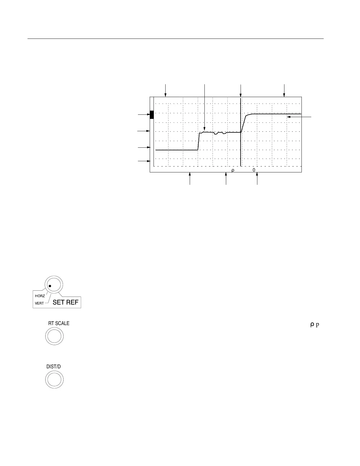
Display
O
F
F
O
F
F
O
F
F
O
N
1 avg
500 m
r
0.2 ft
ac
0.000 ft
Power
Type CursorWaveform
Front-Panel to Cursor
Distance Window
Grid
Selected
Noise Filter
Selected Selected
Vertical Scale Distance per
Division
View Input
Indicator
View Store
View Difference
Store
Indicator
Indicator
Indicator
Figure 1–4: Display and Indicators
Front-Panel Controls
1. CABLE: A female BNC connector for attaching a cable to the 1502C for
testing.
2. NOISE FILTER: If the displayed waveform is noisy, the apparent noise can
be reduced by using noise averaging. Averaging settings are between 1 and 128.
The time for averaging is directly proportional to the averaging setting chosen.
A setting of 128 might take the instrument up to 35 seconds to acquire and
display a waveform. The first two positions on the NOISE FILTER control are
used for setting the vertical and horizontal reference points. The selected value
or function is displayed above the control on the LCD.
3. VERT SCALE: This control sets the vertical sensitivity, displayed in m
r
per
division, or the vertical gain, displayed in dB. Although the instrument defaults
to millirho, you may choose the preferred mode from the Setup Menu. The
selected value is displayed above the control on the LCD.
4. DIST/DIV: Determines the number of feet (or meters) per division across the
display. The minimum setting is 0.1 ft/div (0.025 meters) and the maximum
setting is 200 ft/div (50 meters). The selected value is displayed above the
control on the LCD.
A standard instrument defaults to ft/div. A metric instrument (Option 05)
defaults to m/div, but either may be changed temporarily from the menu. The
default can be changed by changing an internal jumper (see 1502C Service
Manual and always refer such changes to qualified service personnel).
NOISE FILTER
HORZ
VERT SET REF
VERT SCALE
DIST/DIV
Artisan Technology Group - Quality Instrumentation ... Guaranteed | (888) 88-SOURCE | www.artisantg.com