Circuit Descriptions
5–4
1502C MTDR Service Manual
Power Supply
The power supply consists of the following:
H
Primary Circuit
H
Pre-regulator
H
Battery Charger
H
Deep Discharge Protection
H
Port-regulator
H
DC-to-DC Converters
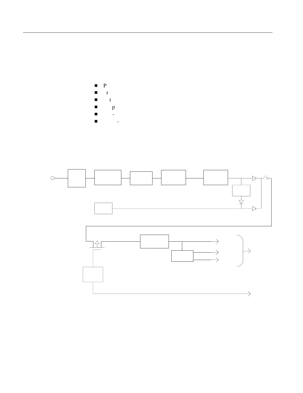
The power supply converts either 115/230 VAC line power, or takes power from a
lead-gel battery, and provides the instrument with regulated DC voltages. A block
diagram of the power supply is shown in Figure 5–3.
Fuse and
Line Select
Switch
EMI
Line
Filter
Step down
XFMR
Rectifier
&
Filter Cap.
Switcher
&
Prereq.
Battery
Charger
Battery
Switcher and
Post–regulator
DC to DC
Converter
Deep
Discharge
Protection
115/230 volt
AC line
+ 30 VDC + 15.8 VDC
Instr.
Pwr.
Switch
+ 12 VDC
+ 10 to 15.5 VDC
Transistor Power Switch + 16.2 VDC
+ 16 VDC
±
5 VDC
±
15 VDC
DC Power
to Instrument
Power
Status
Figure 5–3: Power Supply Block Diagram
Single-phase AC line voltage is applied to the power supply module through a
power plug with internal EMI filter. The filtered line voltage is immediately fused,
routed through a line selector switch and applied to a stepdown transformer. The
transformer secondary voltage is rectified and power switched to power the post
regulator.
Introduction
Artisan Technology Group - Quality Instrumentation ... Guaranteed | (888) 88-SOURCE | www.artisantg.com