Operating Instructions
1–12
1502C MTDR Service Manual
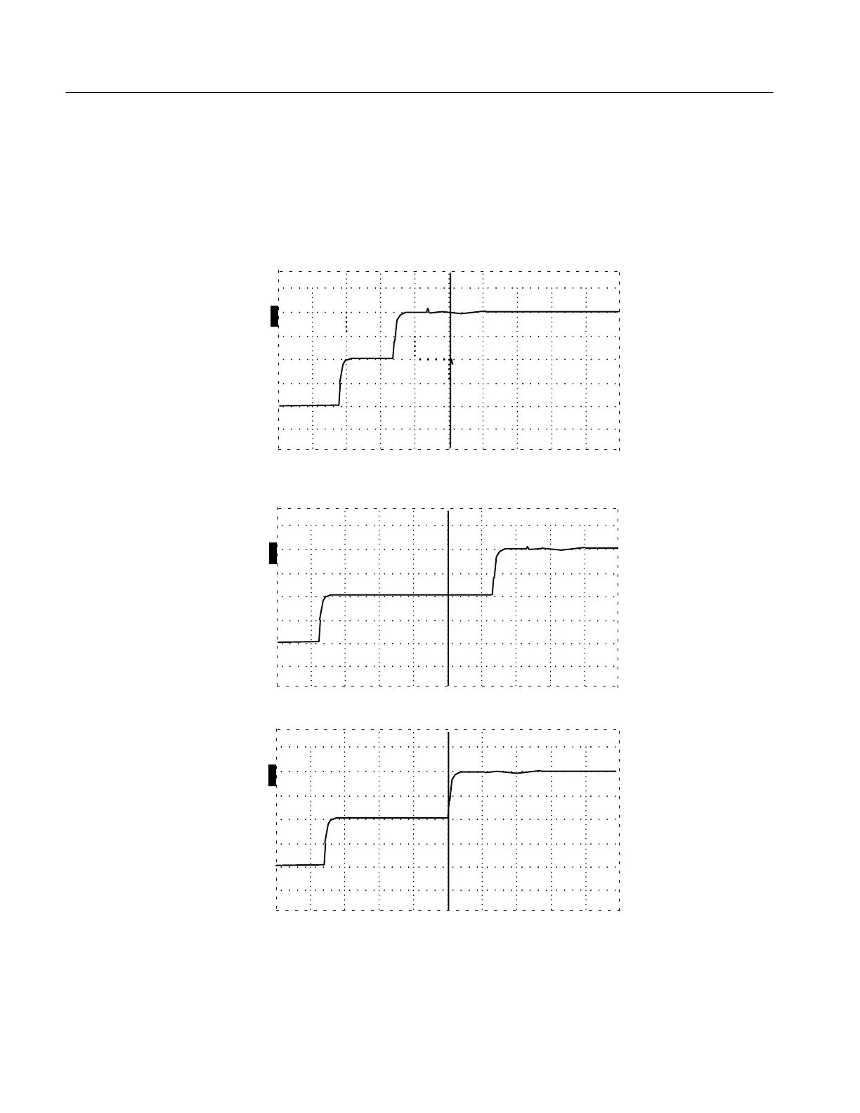
5. Turn the Vp controls until the cursor is resting on the rising portion of the
reflected pulse. The Vp controls of the instrument are now set to the Vp of the
cable.
The following three illustrations show settings too low, too high, and correct for a
sample three-foot cable.
O
F
F
O
F
F
O
F
F
O
N
ac 3.000 ft
Figure 1–5: Vp Set at .30, Cursor Beyond Reflected Pulse (Set Too Low)
O
F
F
O
F
F
O
F
F
O
N
ac 3.000 ft
Figure 1–6: Vp Set at .99, Cursor Less Than Reflected Pulse (Set Too High)
O
F
F
O
F
F
O
F
F
O
N
ac 3.000 ft
Figure 1–7: Vp Set at .66, Cursor at Reflected Pulse (Set Correctly)
Artisan Technology Group - Quality Instrumentation ... Guaranteed | (888) 88-SOURCE | www.artisantg.com